Fabricating Mechanical Automatons
Kinetic Randomness Generator .5
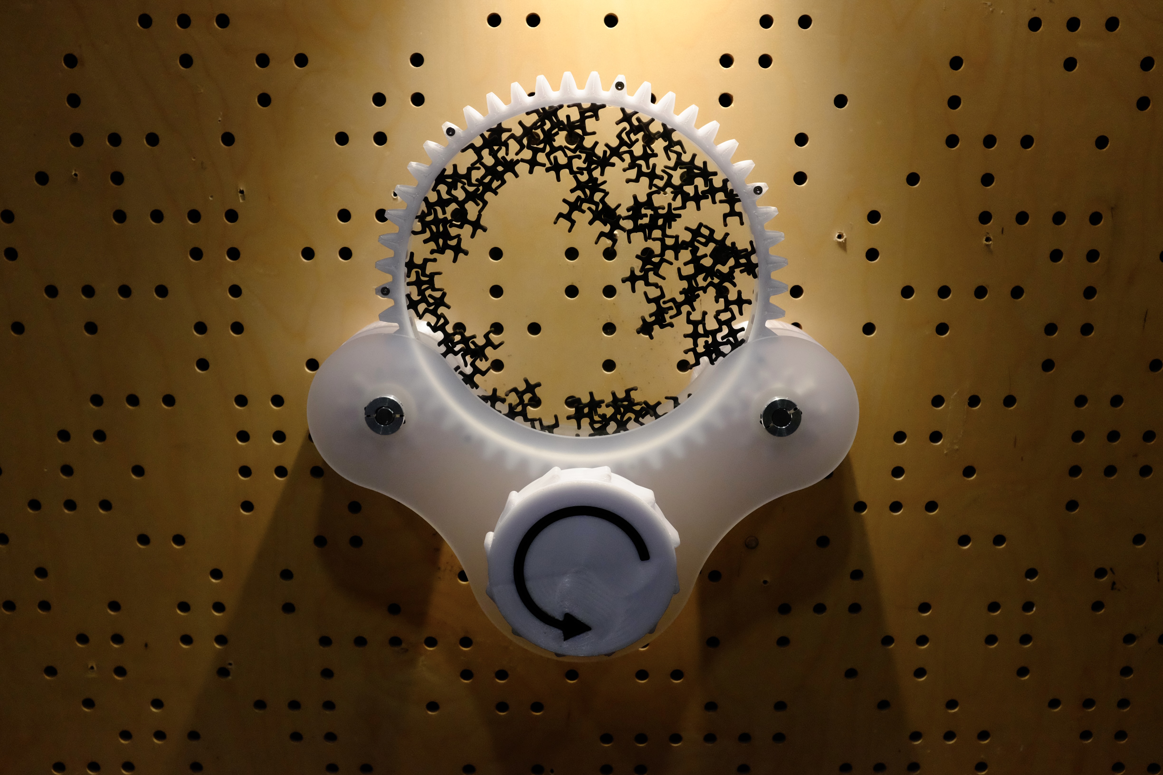
This is the second Kinetic Randomness Generator that I have created. The .5 designation refers to the figurines, a unused artifact from my previous development cycle.
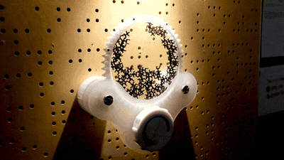
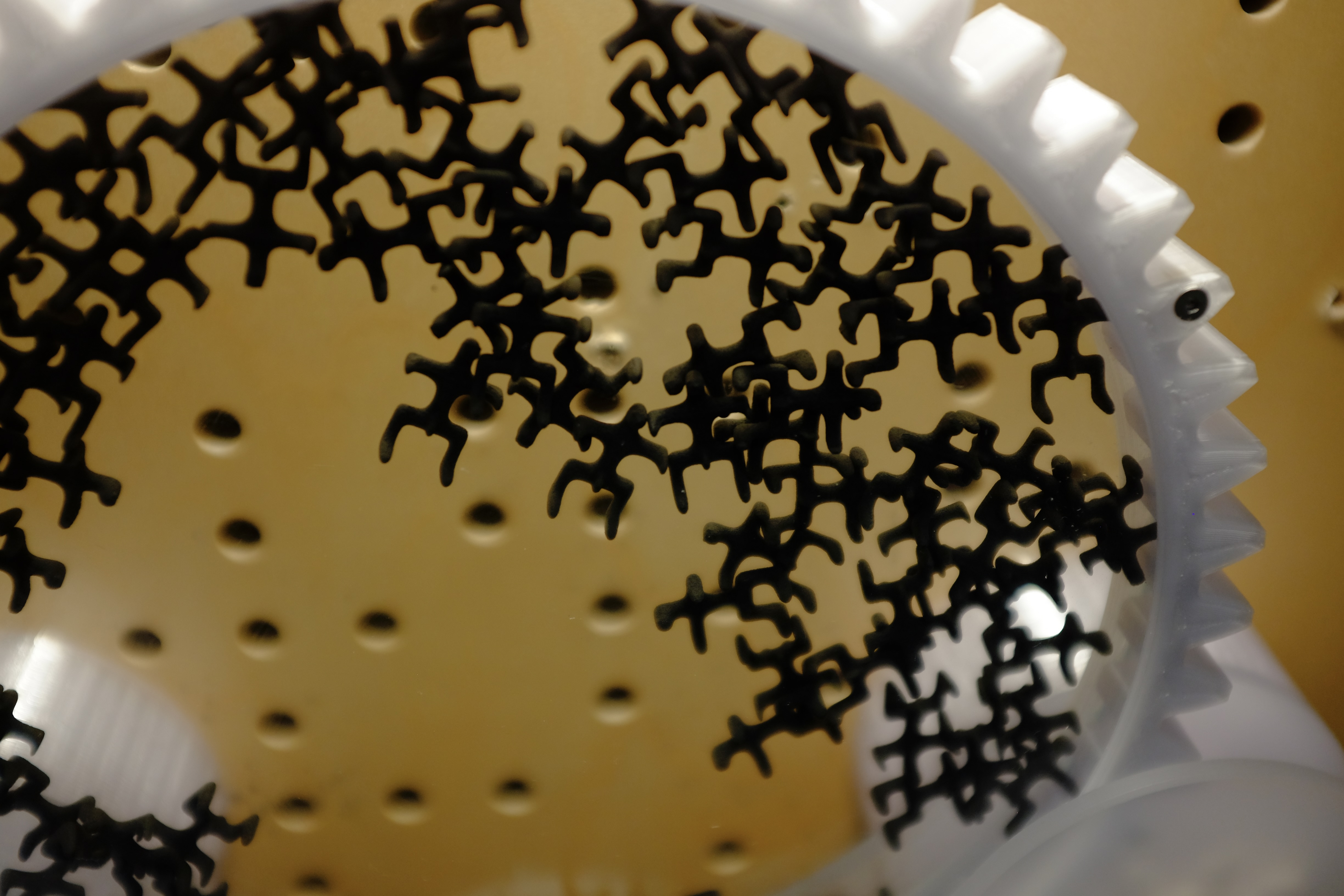
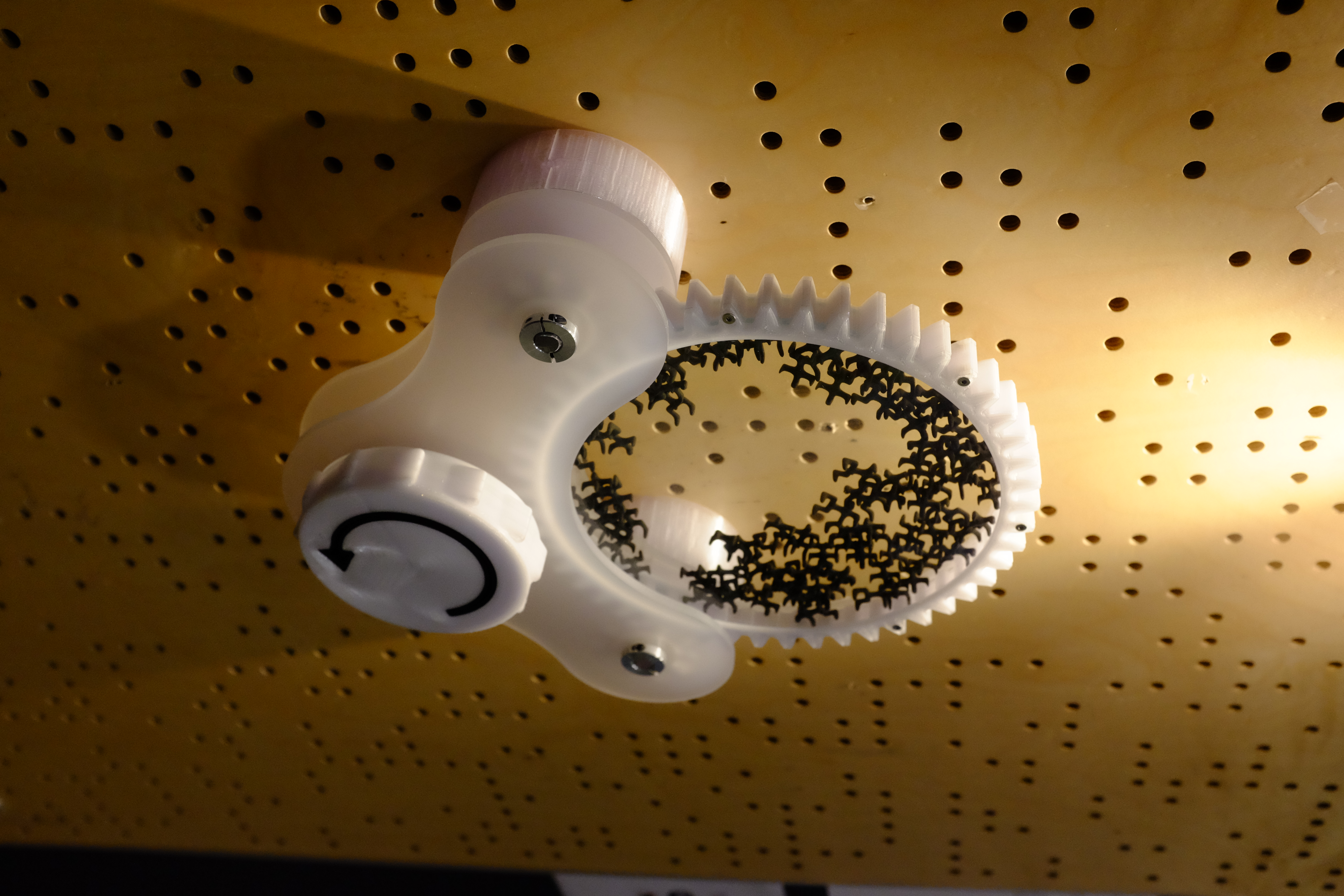
This work is revisiting themes from the previous kinetic randomness generator. Im taking a simple linear (now rotational) input and outputting a complex configuration of figures. I am using the form of a human as my stackable shape because they fit together with some distance. I feel this is how we are as people, random agents in a predetermined system. People tend to get it I think.
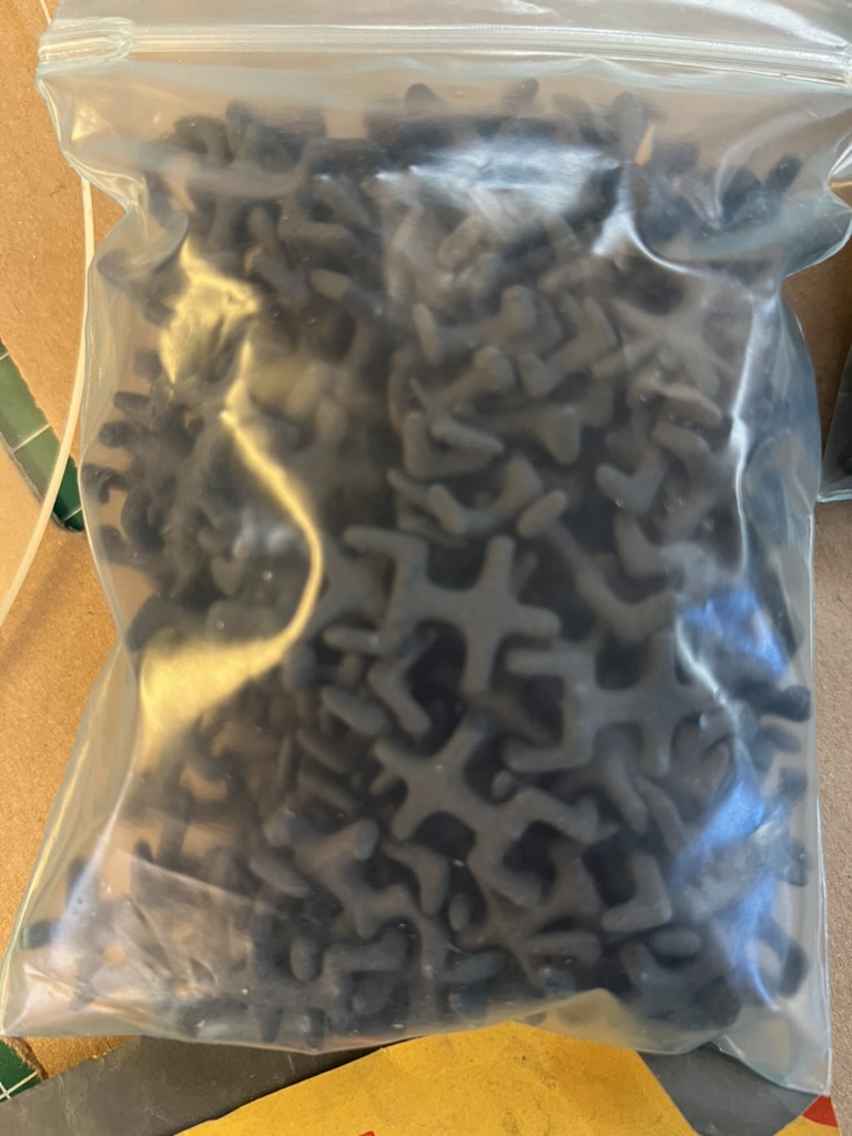
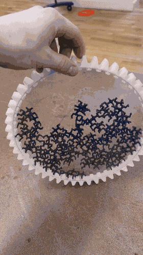
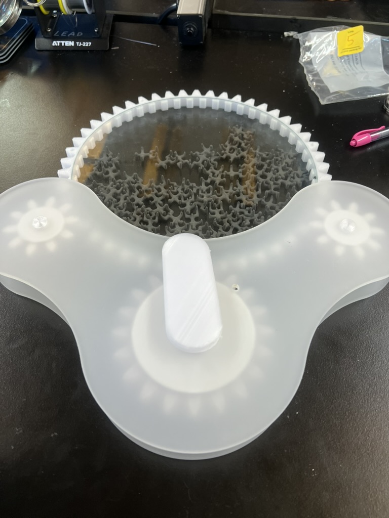
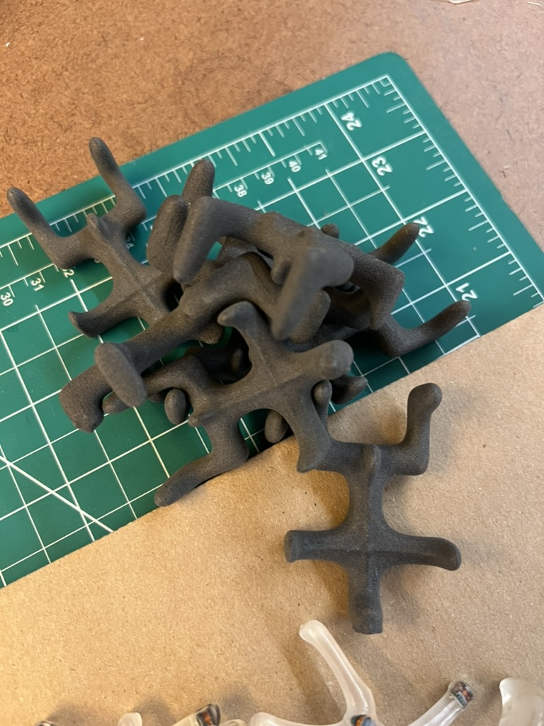
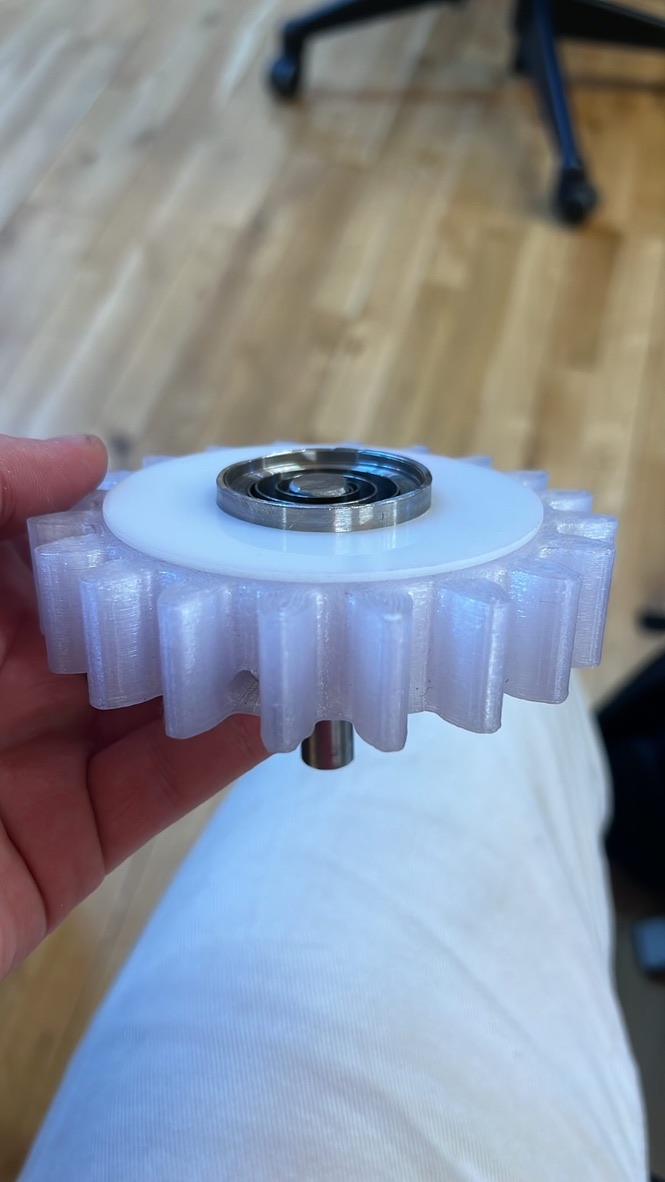
The figurines are leftover from the first KRG development process. I went through many iterations before discovering the imbeded leds as a way to add randomness and control. These prototype figurines were 3D printed on a formlabs Fuse SLS machine using Glass Filled Nylon 12. They feel great in hand and are so strong. I cleaned them all off by hand, back in the day, and kept them. I love them, so I should put them in something. I want to make their uniqueness as an object shine
Ideation
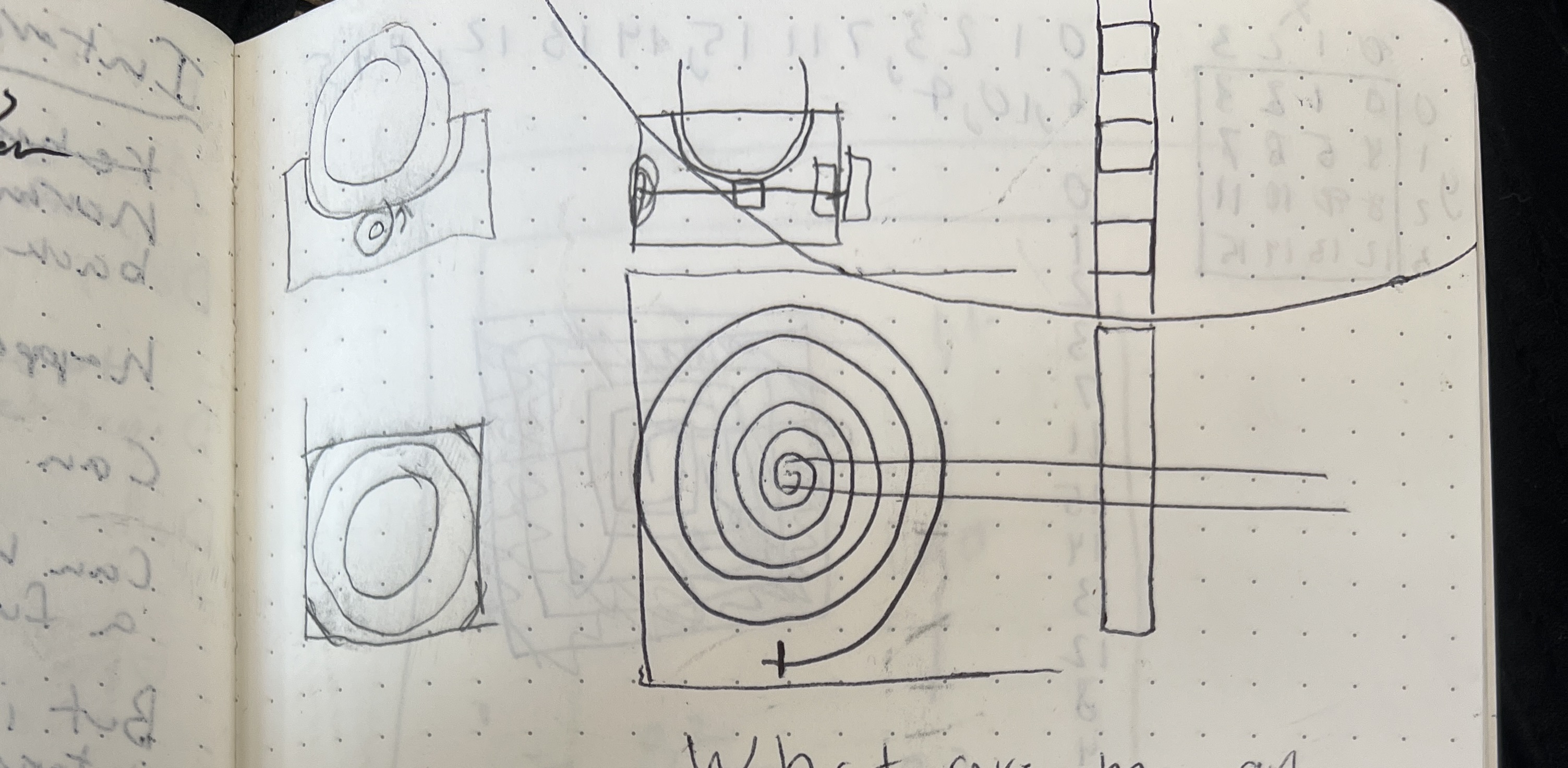
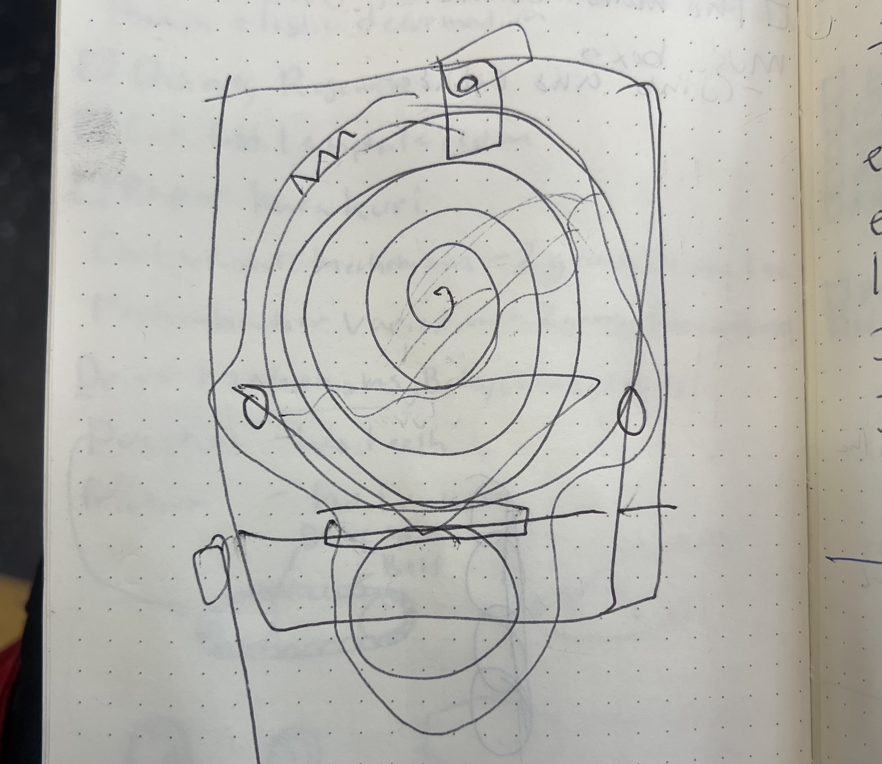
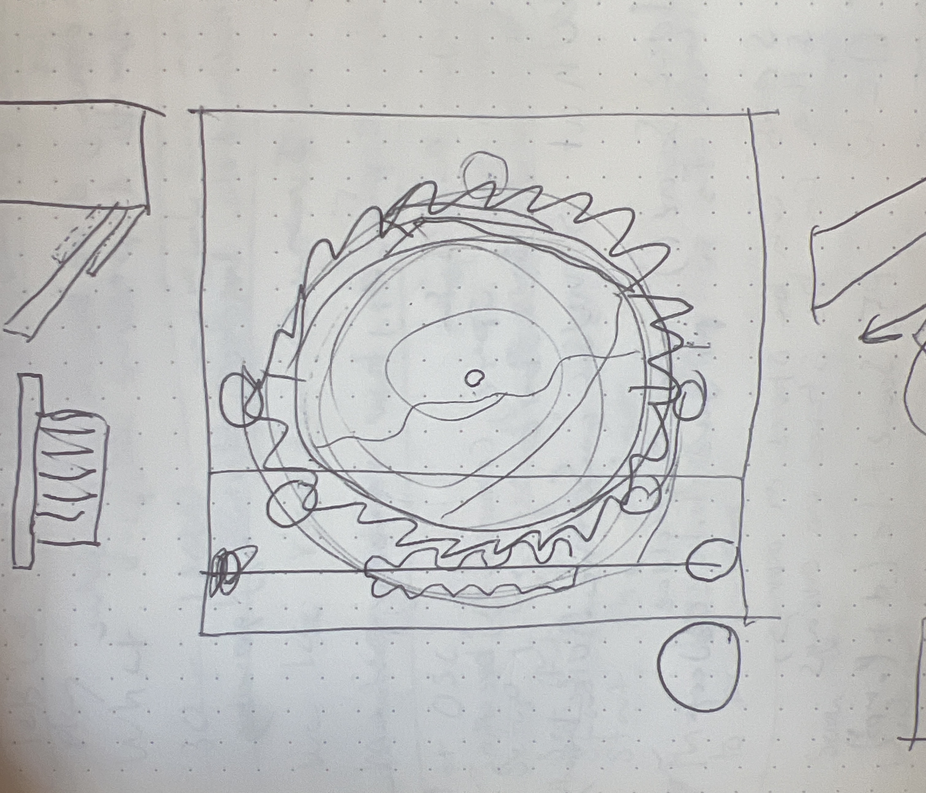
My first sketches frustrated me because I could not get out of the mindset of the orb. As I drew and drew and drew I walked myself back through all the design decisions I had made on the previous iteration! Out of this frustration, I knew I had to capture them differently. I sketched up an interaction where they could be held flat in a pertri-dish and spun and tumble in two dimensions.
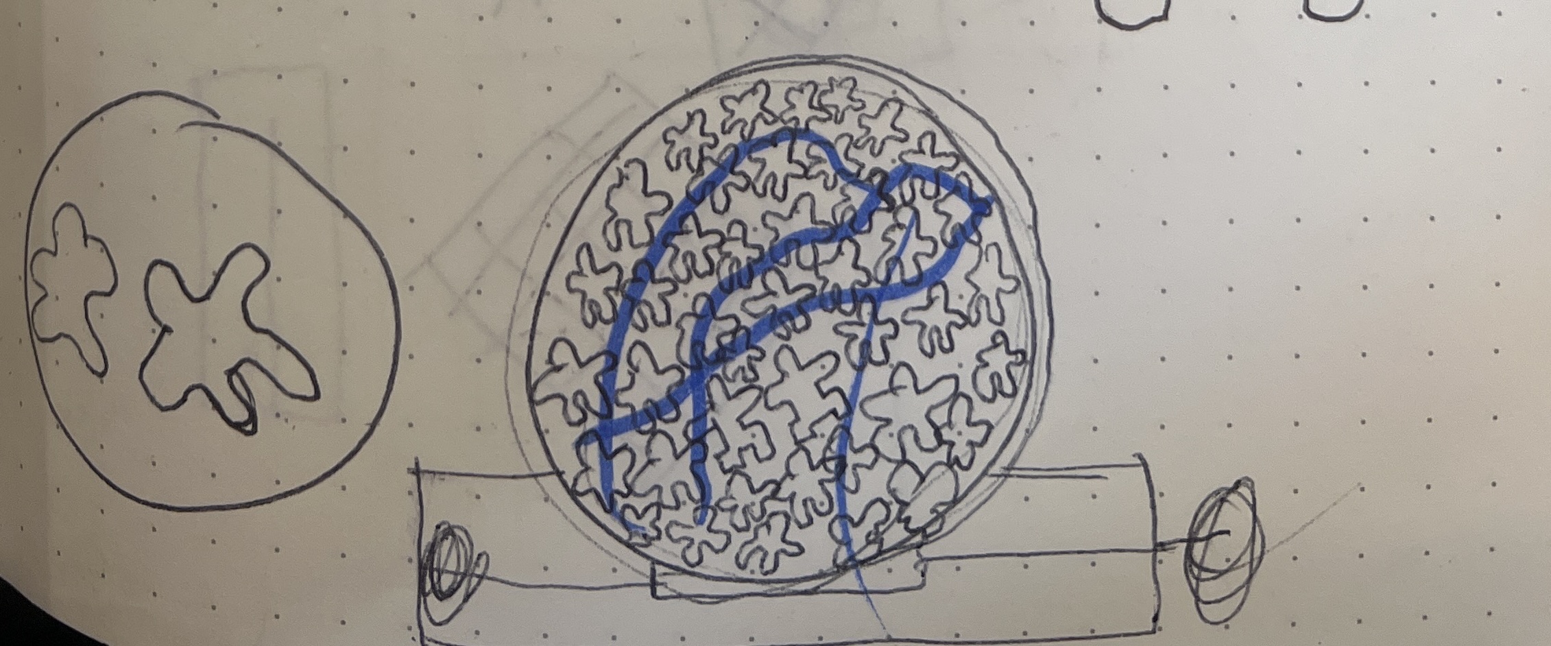
This is where it clicked for me and the whole process of drawing became fun. I realized that by placing them flat against each other I could highlight their silhouettes. Their personness would shine. Also, their distance would be made visible.
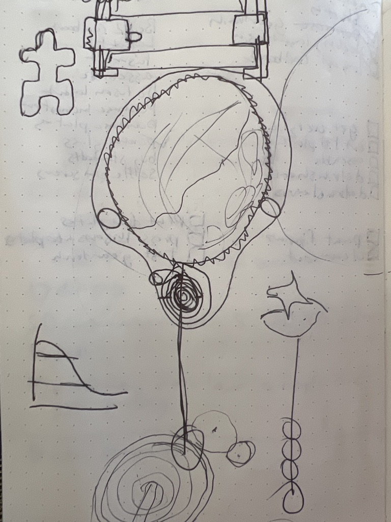
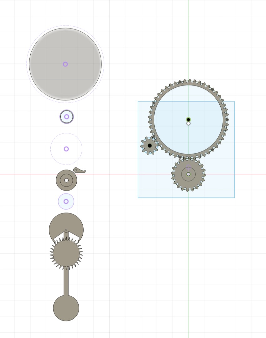
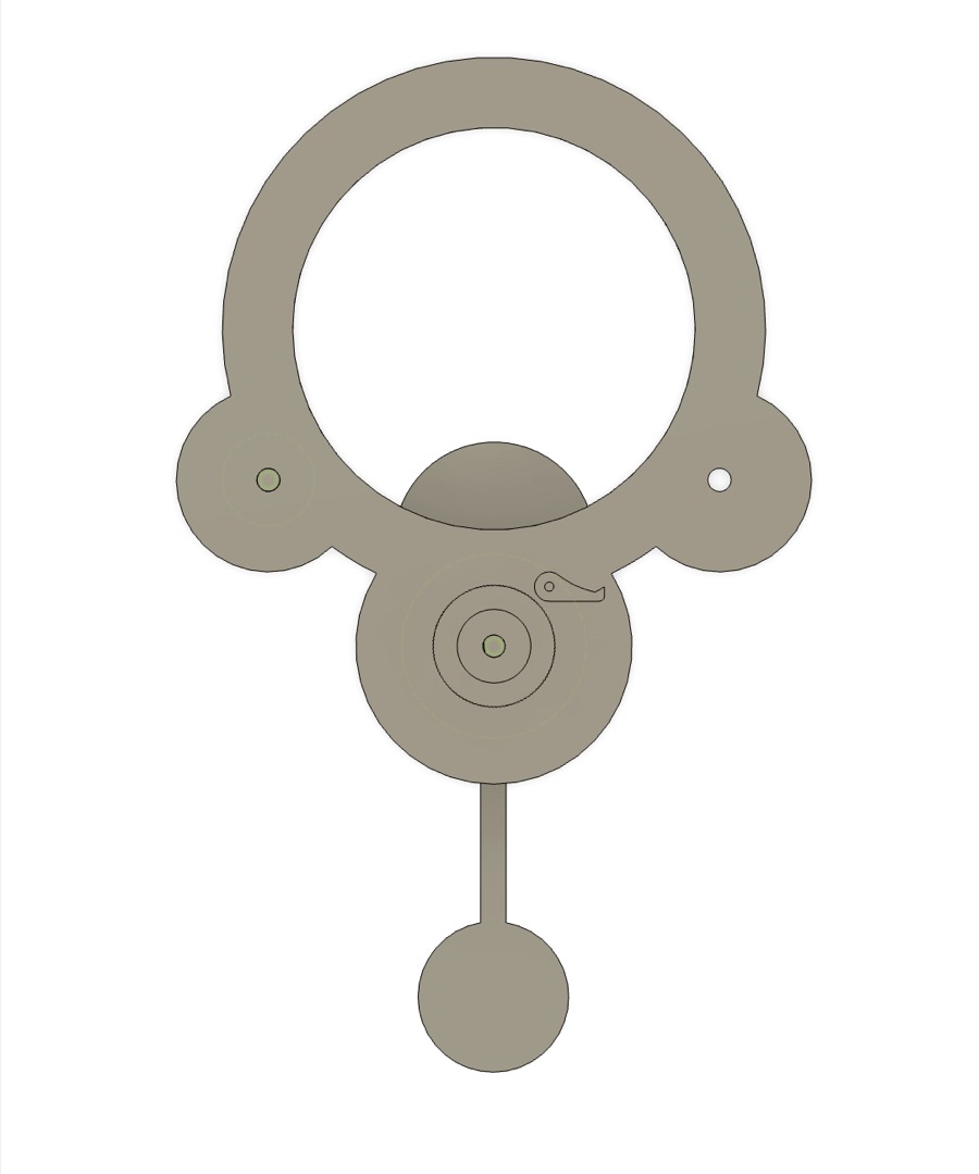
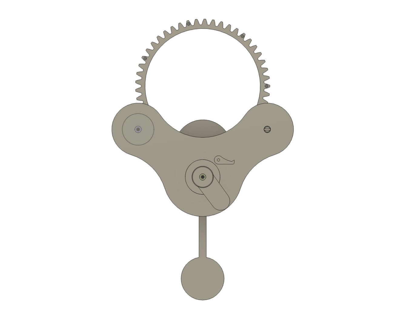
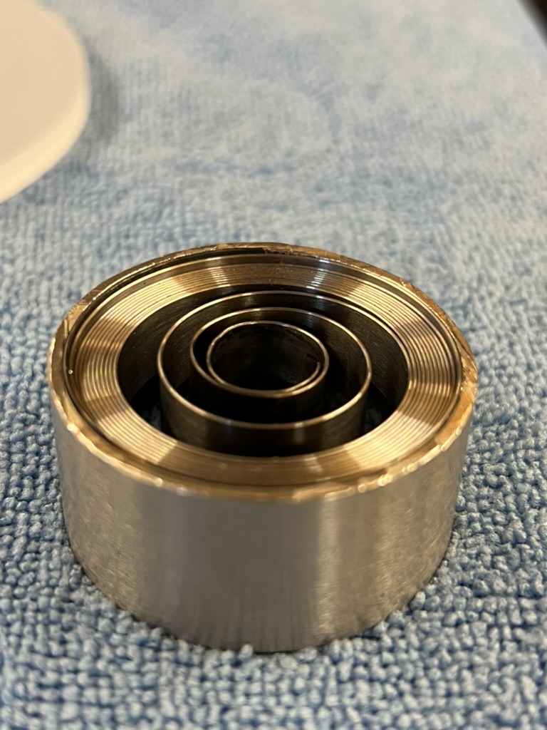
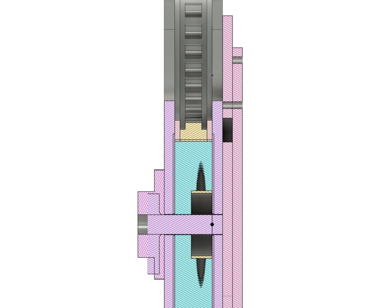
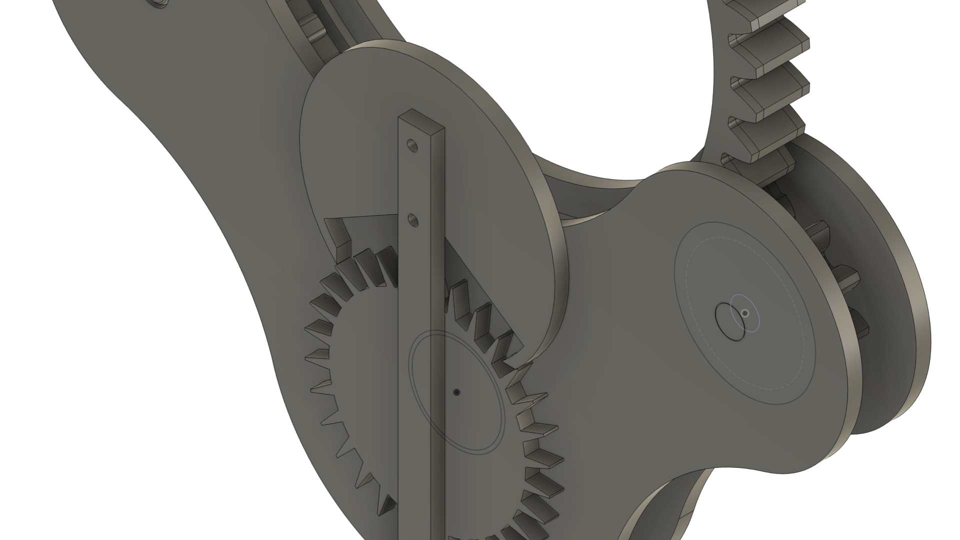
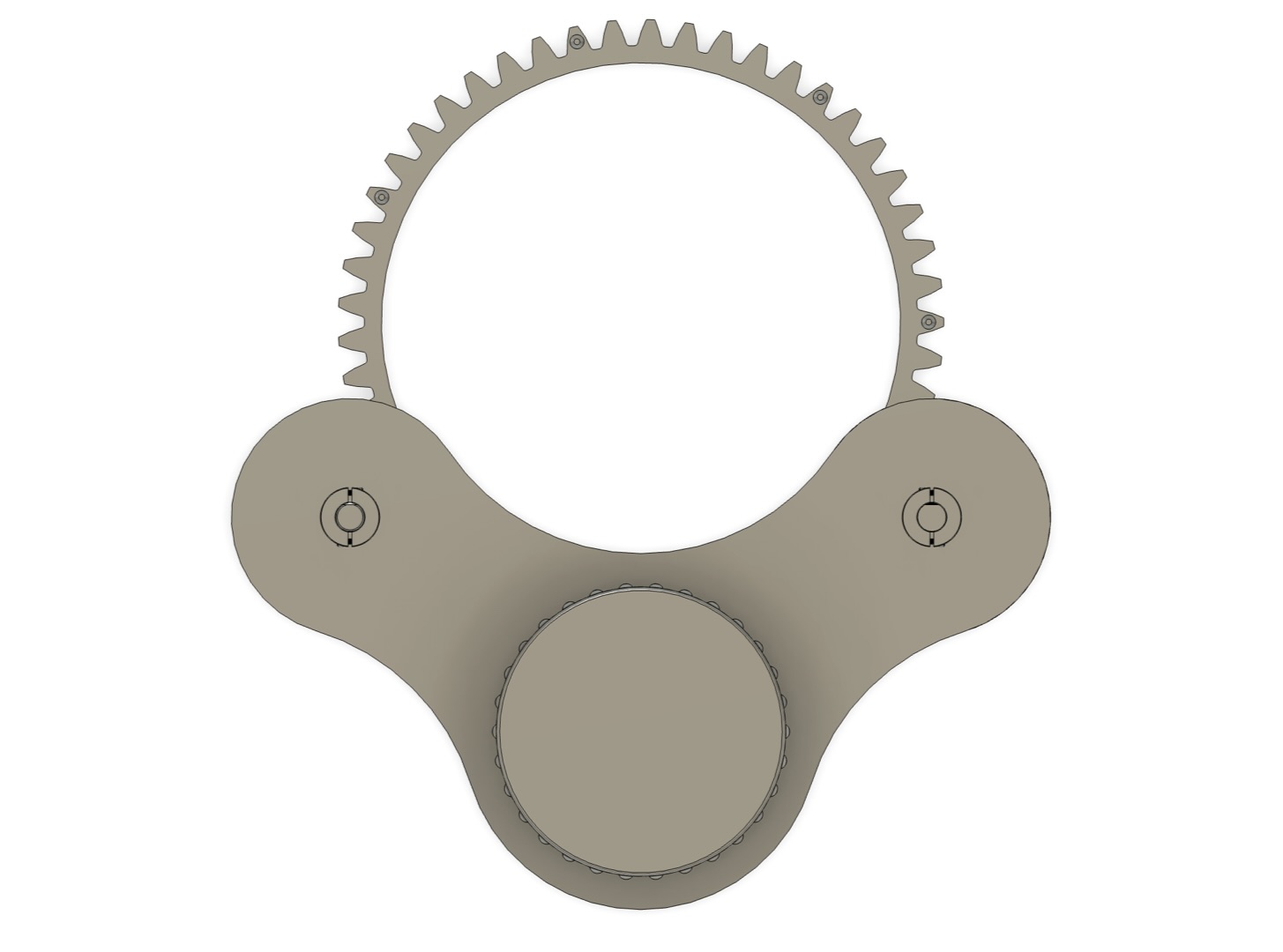
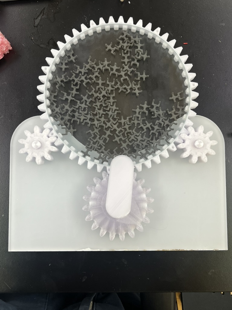
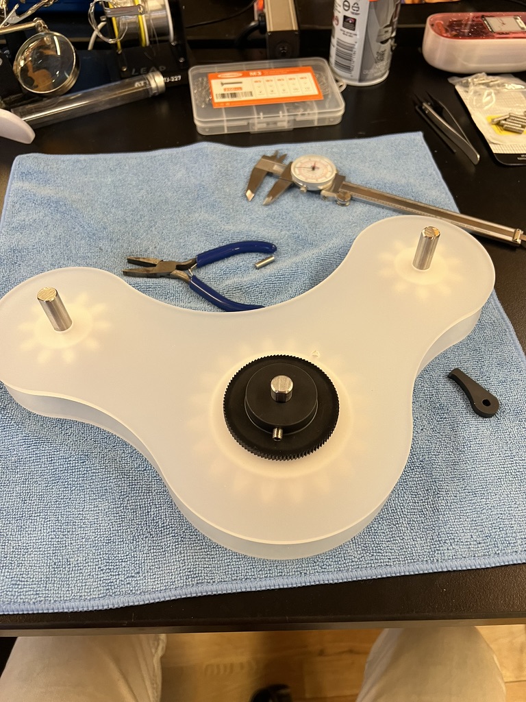
I iterated through a couple ideas on how to get the thing to spin and how exactly it would be an "automaton". I wanted it to spin and recreate itself for a long time, so I needed an energy storage and release mechenism. I also devised three points of contact, hoping to allow me to remove it from the top of the frame.
Prototyping
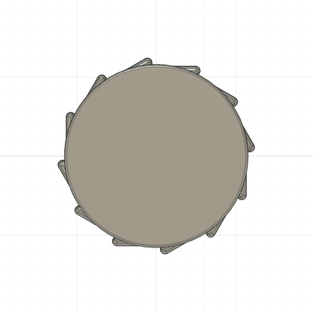
I wanted to work with my most important pieces as parts I could purchase, like the flat glass rounds and the mcmastercarr ratchet. I used lasercut cardboard to bring components into real life space to evaluate their size in my hands.
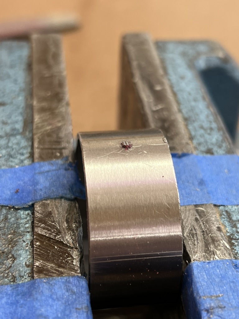
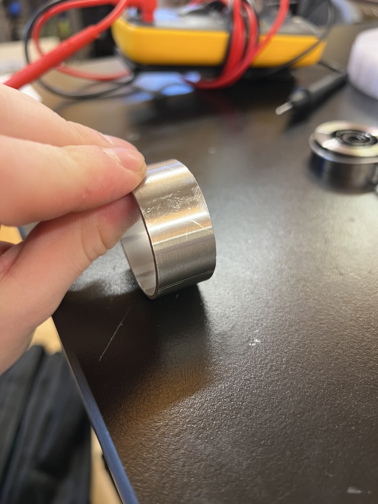
I got into some trouble with the flat glass rounds. When I designed the capture armature to retain them, I assumed they would both be the same size and thus take the same tollorences for a press fit. This assumption was incorrect. I took time to dial in the fit for the first round using 1 printhead thick circumfrence gauges, dialing in my press fit tolorence before commiting to a full mounting piece. After this process, I found that one of my three glass rounds fit perfect and with some pressure, I could get one of the remaining two to press fit as well. The third was out of tollorence to be used, too large.
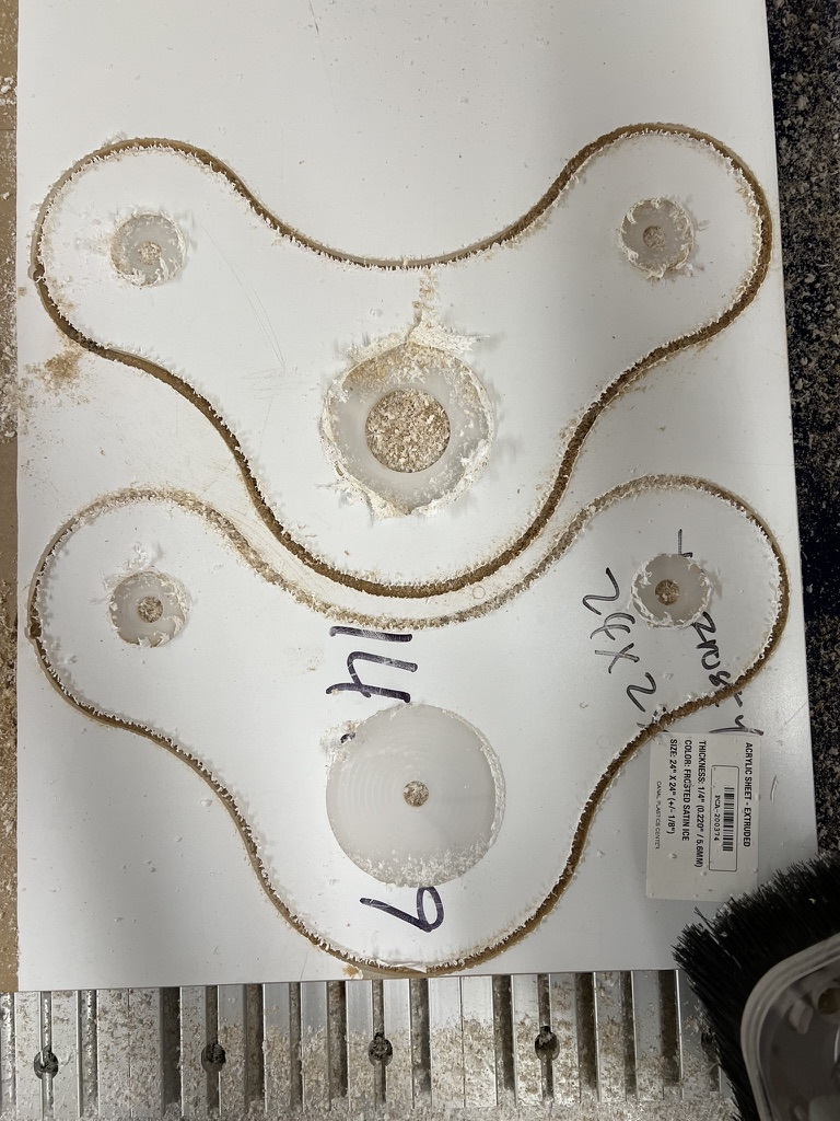
About a month of so before the project was due, I carried the delusion that I had a week less than expected to produce the work. In this period, I wanted to minimize and reduce everything I was doing to ensure that it would work. In this phase, I dropped the pendulum. I had missed my window to get parts cut professionally becuase I had not prototyped enough to be confident with the final piece and needed control over the production process to correct of unforseen mistakes.
Pretty early on I was able to get something quick and dirty that showed the final concept in action. In this handheld prototype I was able to demonstrate the movement I wanted to get.
Assembly
I moved into the final assembly in the last week before the project was due, having planned well but feeling dreadfull. Something about putting it together and seeing if it worked was blocking me mentally.
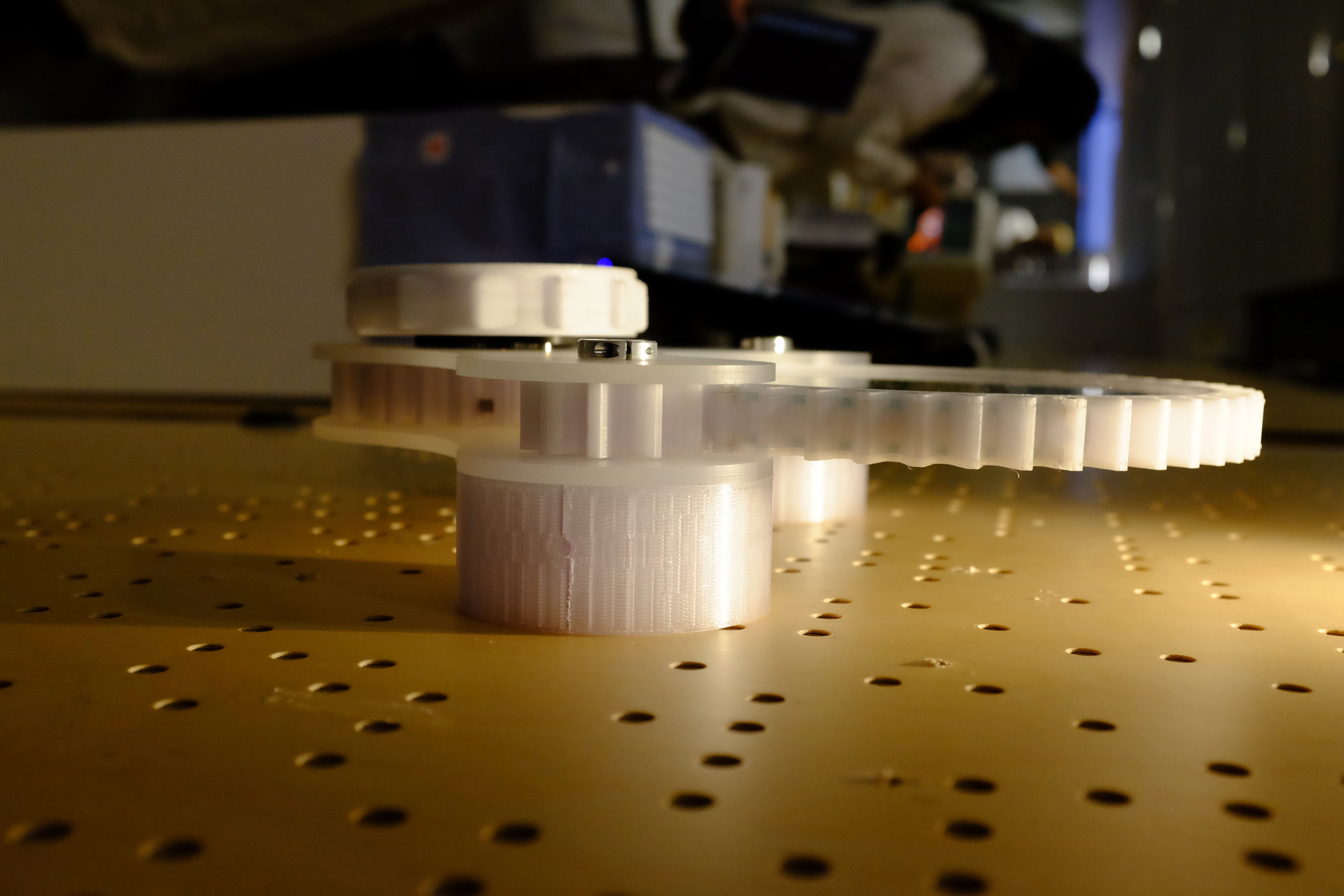
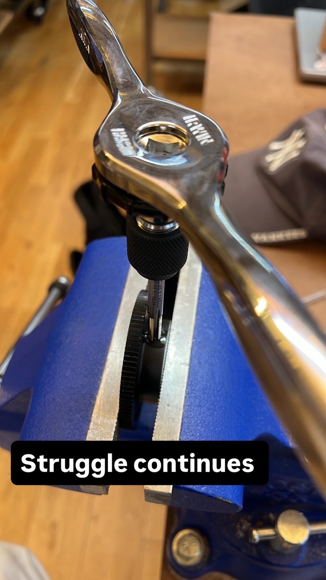
One of the most fun (and mentally blocking parts) was cutting the rod to length. In my mind I had it built up like the precision of the cut mattered a lot. I realized after that I had no requirement for linear precision becuase it was not a mating surface or a reference plane. The most important radial reference was already established. I cut my rod lengths for the supporting rotational gears with cutting fluid and the metal blade chop saw. I used the rotating sander to put a fine champfer on the ends when I cut them to length. This was my favoriter part
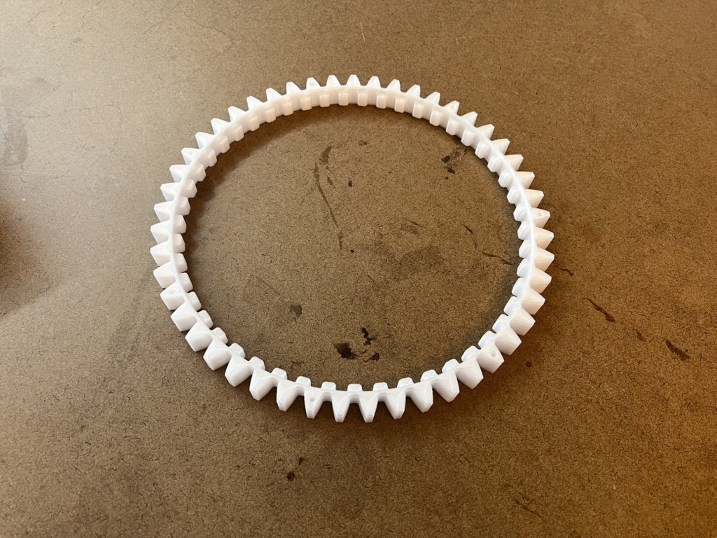
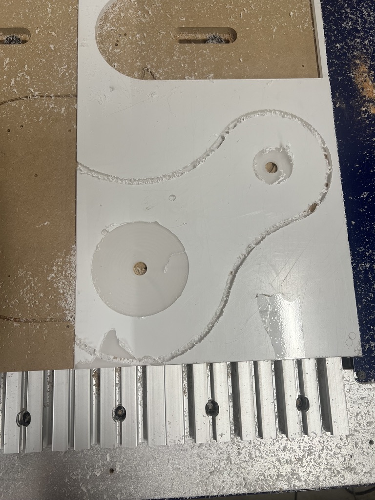
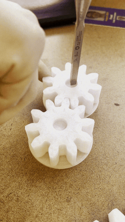
I also cut the acrylic on the cnc machine so I could make holes and pockets. I wanted the delrin surface the gears rode on to be placed smoothly.
As I put the pieces I had made together, I realized the piece I had made would not rotate. I had previously made the retaining plate for my rotational chamber an eigth of an inch so I could create it from lasercut acrylic. Now I was just producing it on the 3d printer. Another problem I had when it was all together was the protrusion of the flat m3 screws. They were not indented enough to be flush. Increasing these two aspects, as well as shimming my delrin with layers of sticky tape, reduced the friction enough so that the rotational aspect of the piece could operate
Documentation

Reflection
In the end this project was just like my very first assignment in this class, velocicar!