Intangible Interaction — Professor Yeseul Song
Dimmy the Cube: Build Log
created with William Yao @ thewilliamyao.com
The assignment is called curious cube, our goal is to make a cube which exhibits some behavior to be discovered by the user, a nondescript cube with some "personality". I was sitting next to William and said, lets make it walk.
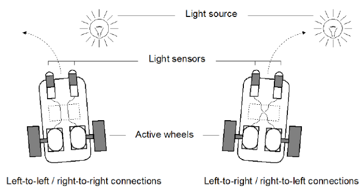
My mind goes to Synthetic Psychology, a landmark book in theory of mind AND robotics by Italian cybernetician Valentino Braitenberg. The 1984 classic describes a series of thought experiments where simple "vehicles" are made which exhibit complex behaviors. It's dense and theoretical and requires constant use of our imaginative powers to comprehend. The book begins by describing a simple vehicle with two sensors and two motors. First we imagine one light sensor is wired to one motor. This vehicle as the sensor goes high, so does the motor, and the vehicle steers away from the light. Then we imagine another with its connectors crossed, now, as the sensor goes high, the opposing motor does as well. The behavior exhibited is remarkably different! As we put the case back on the top and conceal the connections, we might imagine one vehicle as being attracted to light, and the other being repulsed by it. A photophobe and a photoamore. Suddenly, we are not just looking at machines, but thinking things with distinct personalities and drives.
Braitenberg constructs these thought experiments ultimately to examine how animal brains are constructed, his specialty being the anatomy of the fly. Through stacks on stacks of these behaviors, we see more and more complex drives, desires, and even personalities arise from very simple input and output machines. Braitenberg posits intelligence as a secondary trait we construct on top of simple creatures. We turn on the light in the kitchen and the roach runs to cover. It's afraid of the light.
BEAM robotics takes these ideas literally and RUNS WITH IT. Mark Tilden, goated roboticist, coined the term in 1990, with the most widely accepted meaning as Biology, Electronics, Aesthetics and Mechanics. Heavily influenced by Braitenberg, Tilden sought to make real the thought experiments described above using simple analog circuits. Beam robots consist of behavioral stacks built with basic circuits. We can look to early "bump and run" Roombas as the pinnacle commercial example. Although they are no longer simple and analog, their behavioral loop is simple while accomplishing a complex task. Bump a wall, then turn, then bump, then turn, then RUN. Its just a couple sensors and motors. The whole time, the vacuum is running. Even here, people begin to see some intelligence in the thing, emphasizing when their movement is thwarted.
So then, we see a gateway to expressive behavior and the perception of intelligence for our cube. Of all the beam behaviors I find the aversion to light to be the most attractive given its wide adoption among animal life. We chose to build our curious cube around a photo sensor. As we discussed our initial steps, William suggested the cube as a lamp, seeking out the darkest part of a room and illuminating it. To me, this revelation, the addition of a task to its simple drive, give our cube DESIRE. it has a goal.
Rodney Brooks speaks of imbedding a robots intelligence into its physical nature. In this way, the cube is uniquely suited to navigate between light and dark environments. Given the existence of light in the world, we can rely on the formation of shadows in anything but perfect studio lighting. The cube itself, its 5 exposed sides, must always be partially shadowed. As it continues through its desired path, exposed sides will be newly shadowed, making its sequence obvious to it, but mysterious to us.
Its impossible to think of robotic cubes without Cubli coming to mind. this is a control project from ETH Zurich under development from 2013 to 2016. Cubli used three motors, each tied to a reaction which when suddenly stopped, caused the cube to bounce up onto its edge, and then to a single vertex. This is such an engineering impulse, to create and solve a control problem. I felt inspired to be going beyond the previous work done to push the object into the space of intelligence.
Continuing to dig, another project crossed my path, this time by MIT, the M-Block. This one focusing on modular self assembly with collections of cubes able to stick together with magnets Another motor and brake combo. I really didn't want to design for 6 motors.
then came salvation. I found a version of the Cubli which was open sourced and sold as a toy by chinese maker NIKOLATOY. They had slimmed down to design and made it operate with ONLY bldc motors, braking them to cause the impulse and jump up. I needed to learn about these motors they were using, the BLDC. This defined my early work in the project, researching BLDC. But at the same time, we needed to test the basic form.
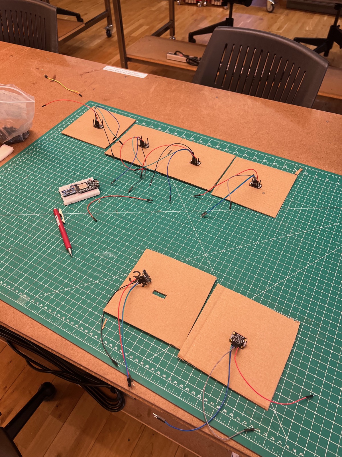
I got some sensors to detect light with and make a basic cardboard box to mount them to. This construct allows us to roleplay the behavior of the cube.
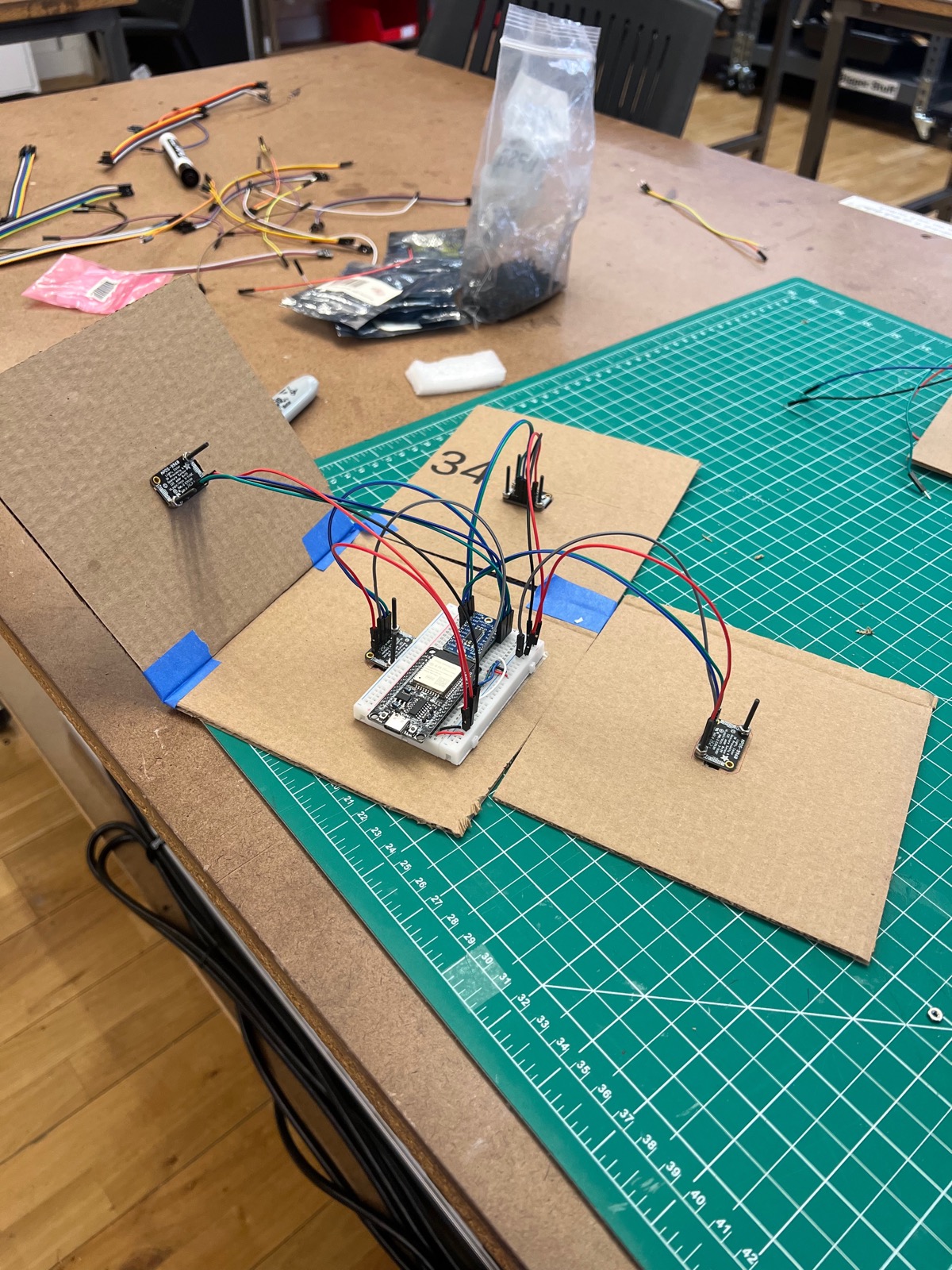
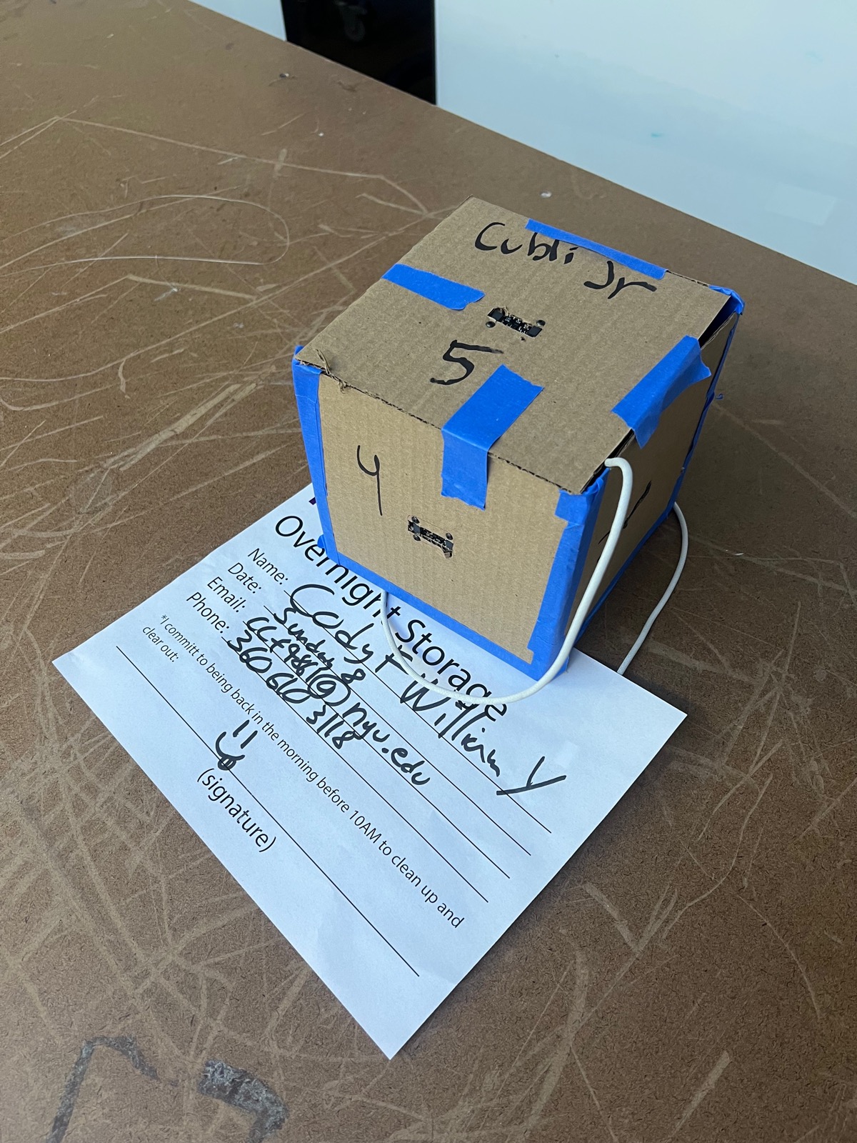
The video below shows the cube in action, demonstrating its ability to move and respond to its environment.
Next we had to figure out how to spin the bldc motors. I went into the theory of their control, learning the differences between a basic BLDC ESC (Electronic Speed Controller) and FOC (field oriented control). An ESC just spins the motor blindly, FOC uses a sensor to close the control loop and push the motor into a specific position. FOC is more complex but provides better control and efficiency. Ultimately, all we needed was BLDC for the reaction wheel. We got practice spinning a lot of motors.
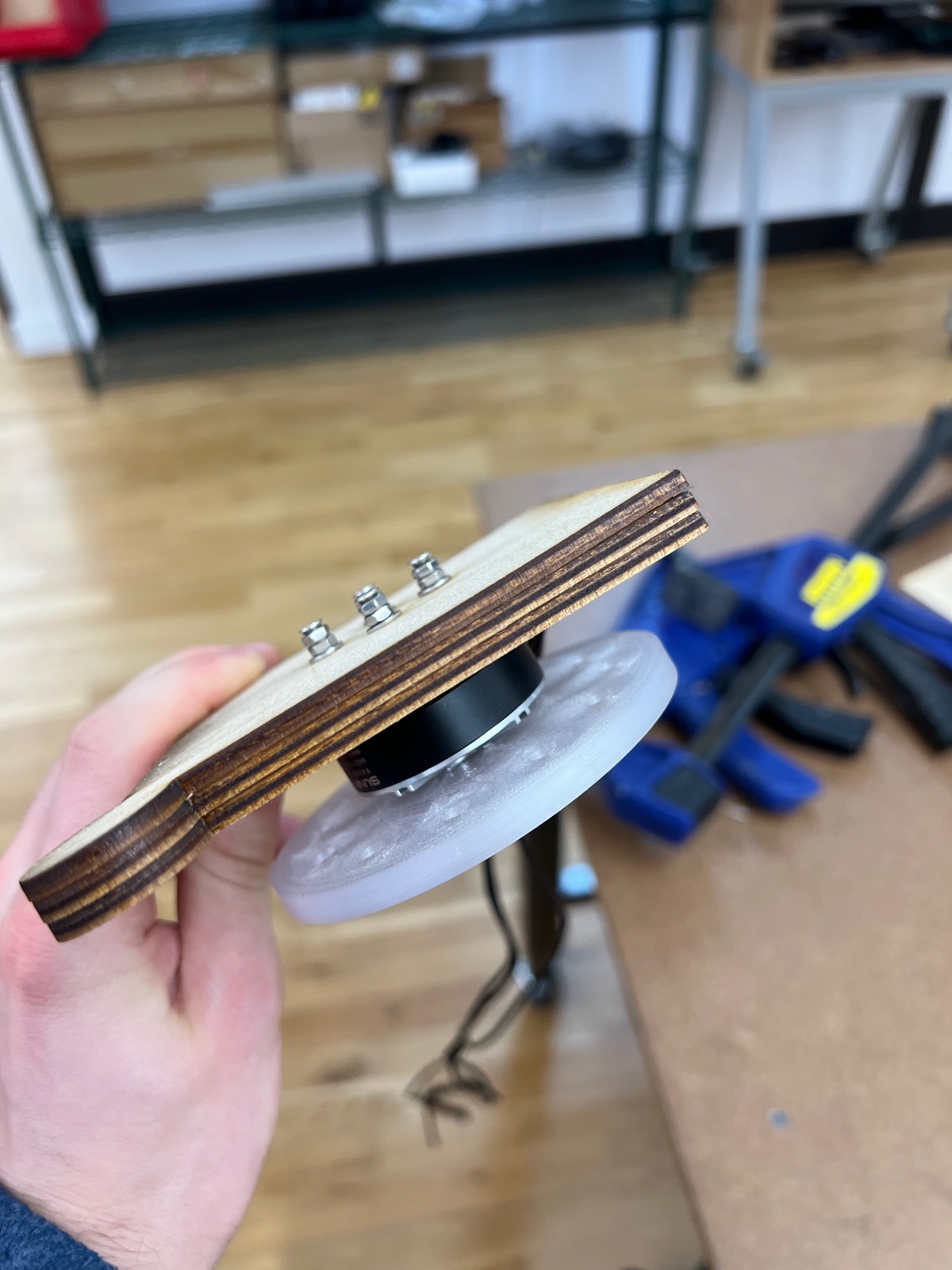
I made this little wood cutout with the shape of the cube to help us see how the reaction wheel mounting would turn out. The reaction wheel was super powerful.
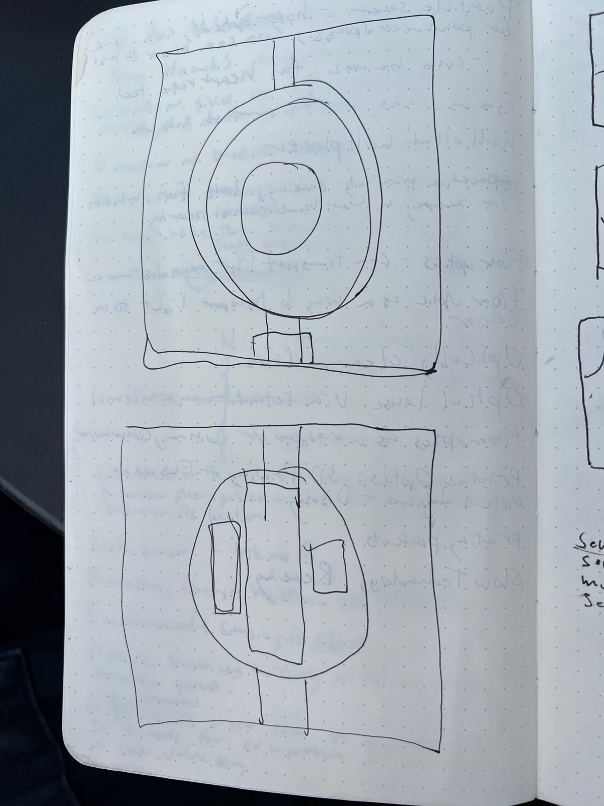
Around this time, I started to think about the overall design and how to minimize the number of motors. I started to sketch ideas where the reaction motor would be on the middle, with its angle controlled by a gimbal. Since our robot was more about locomotion than balance, we didnt need as many motors to throw it in the right direction.
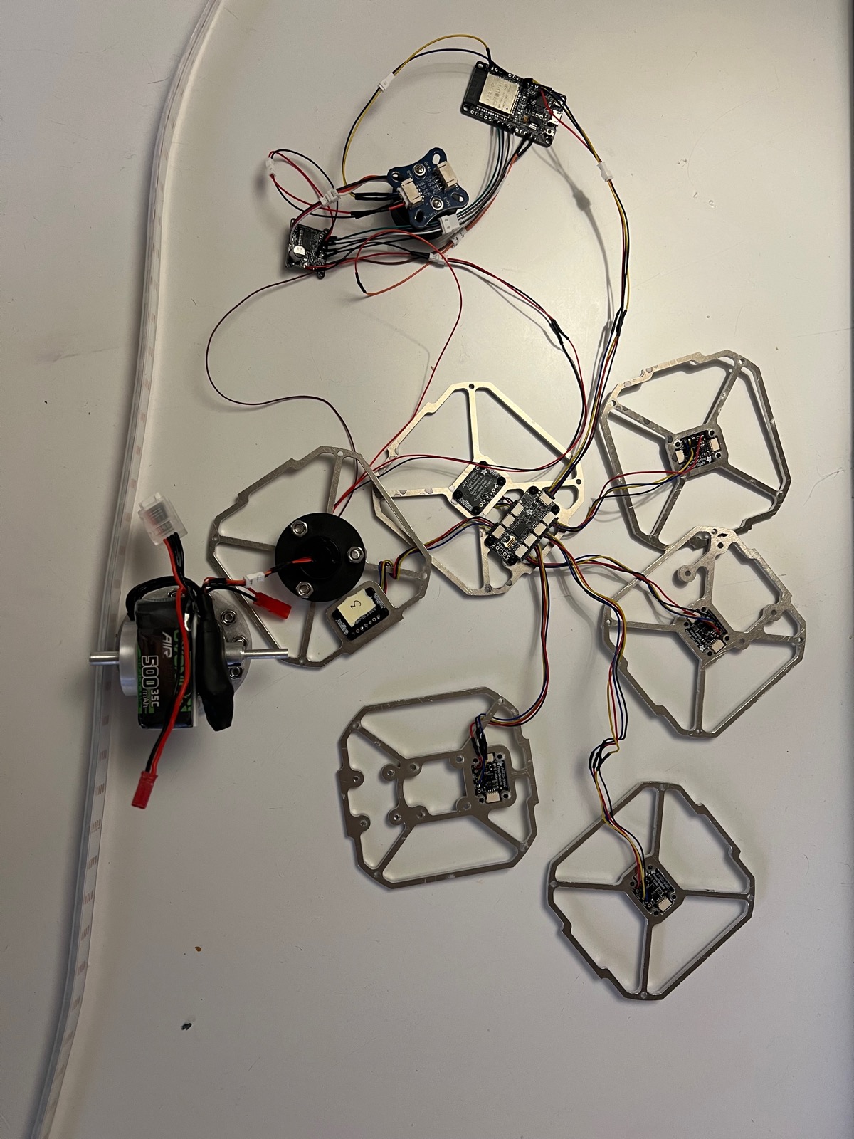
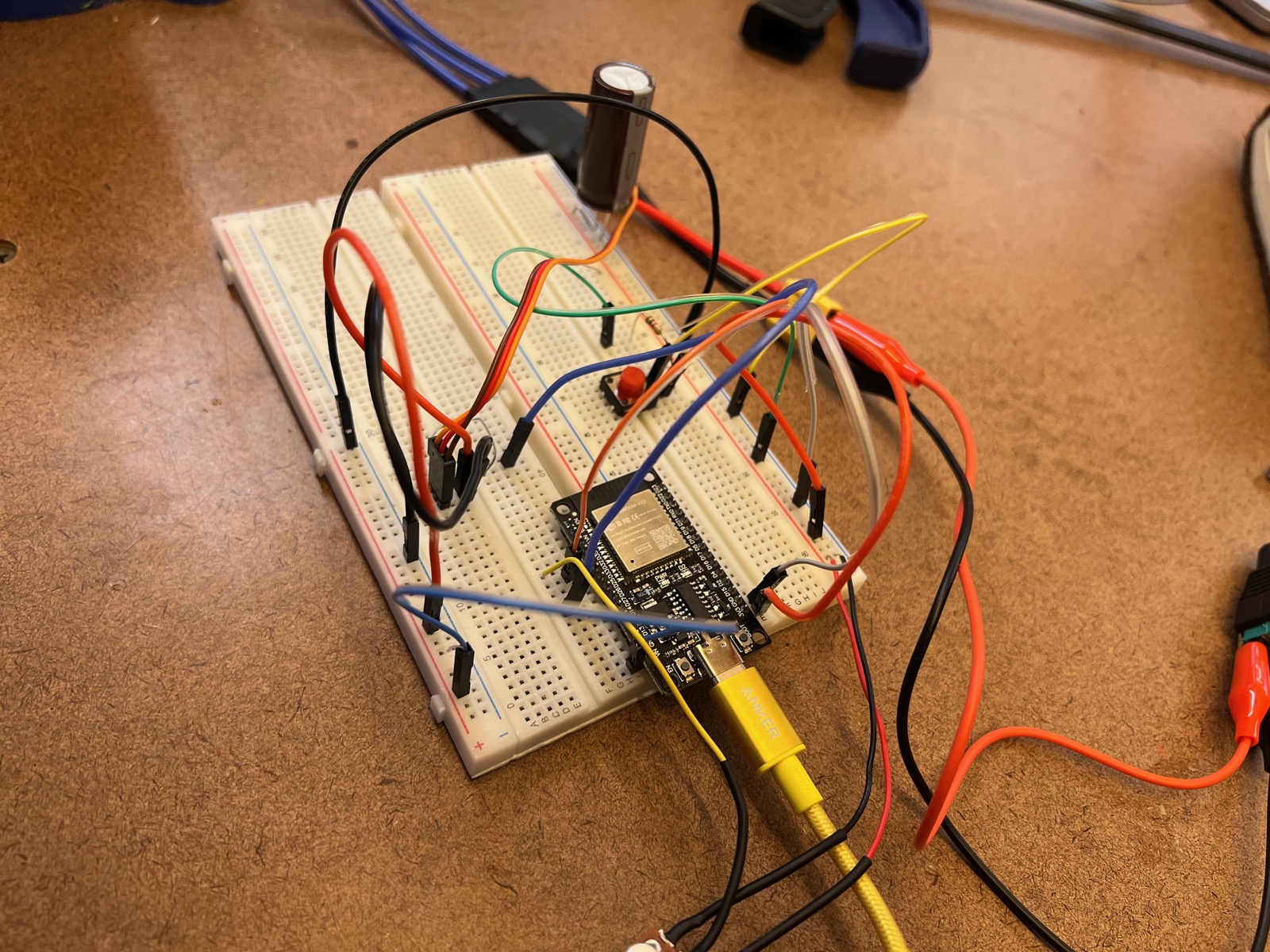
The circuitry for this is a pain in the butt. In this breadboard, were integrating a motor power supply, a potentiometer, and a bldc esc.
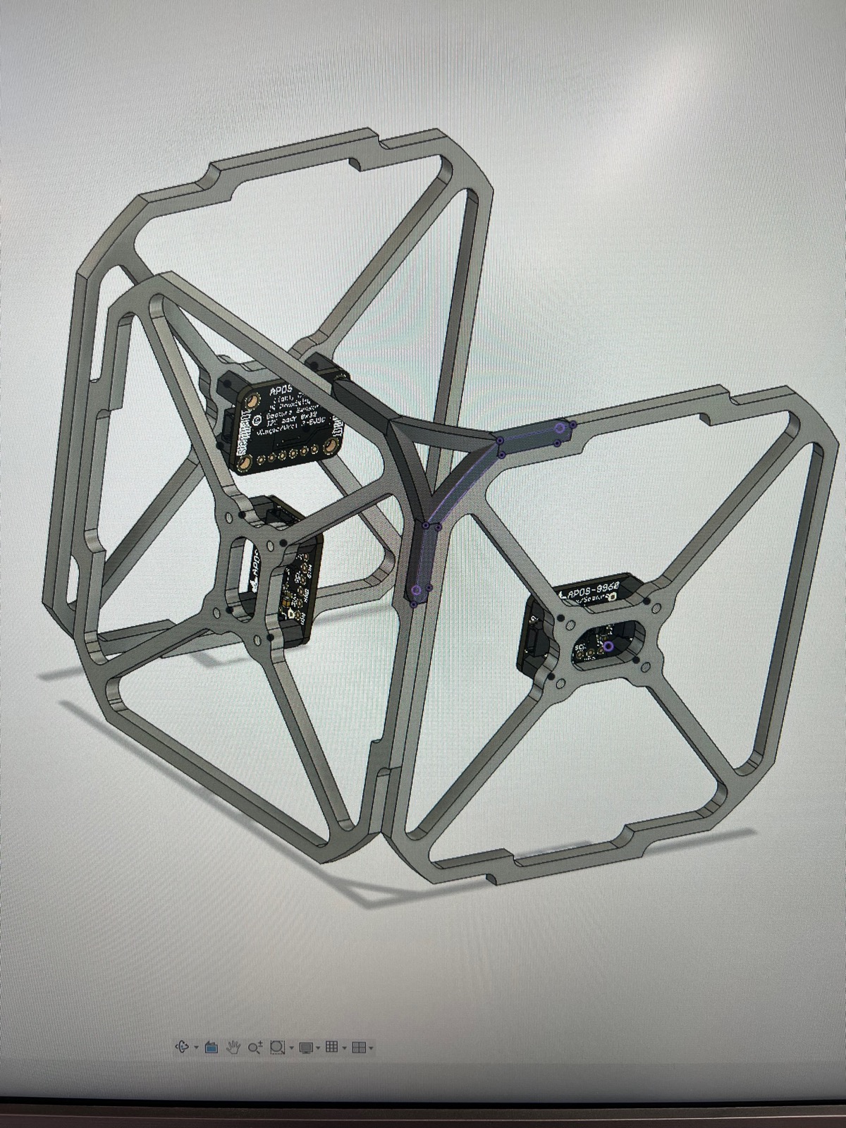
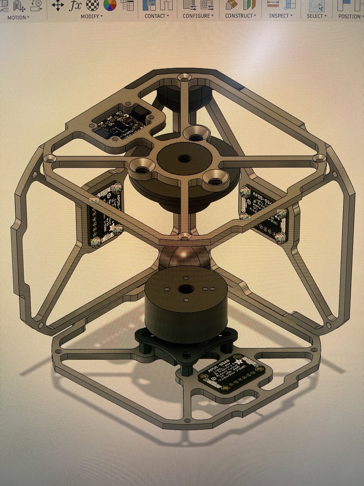
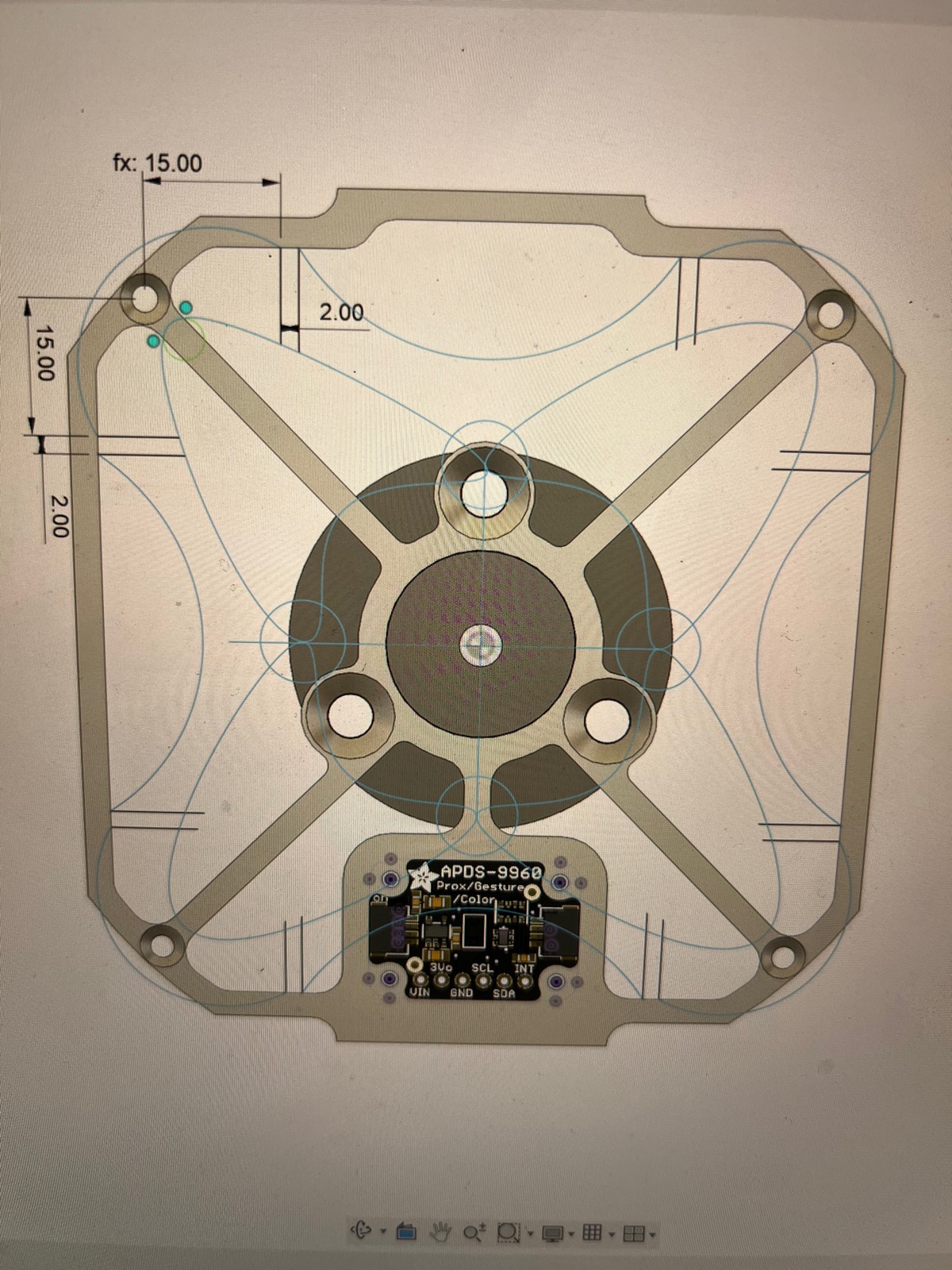
I started to mock up some of the geometry for the sides of the cube. Some of it was obvious, like positioning the sensor boards on the center of the face. It was more difficult to wrap my head around the overlapping tabs on the chassis and the geometry of the corners.
On the other track, we had the motor flipping up the target weight of the robotic assembly with the reaction wheel.
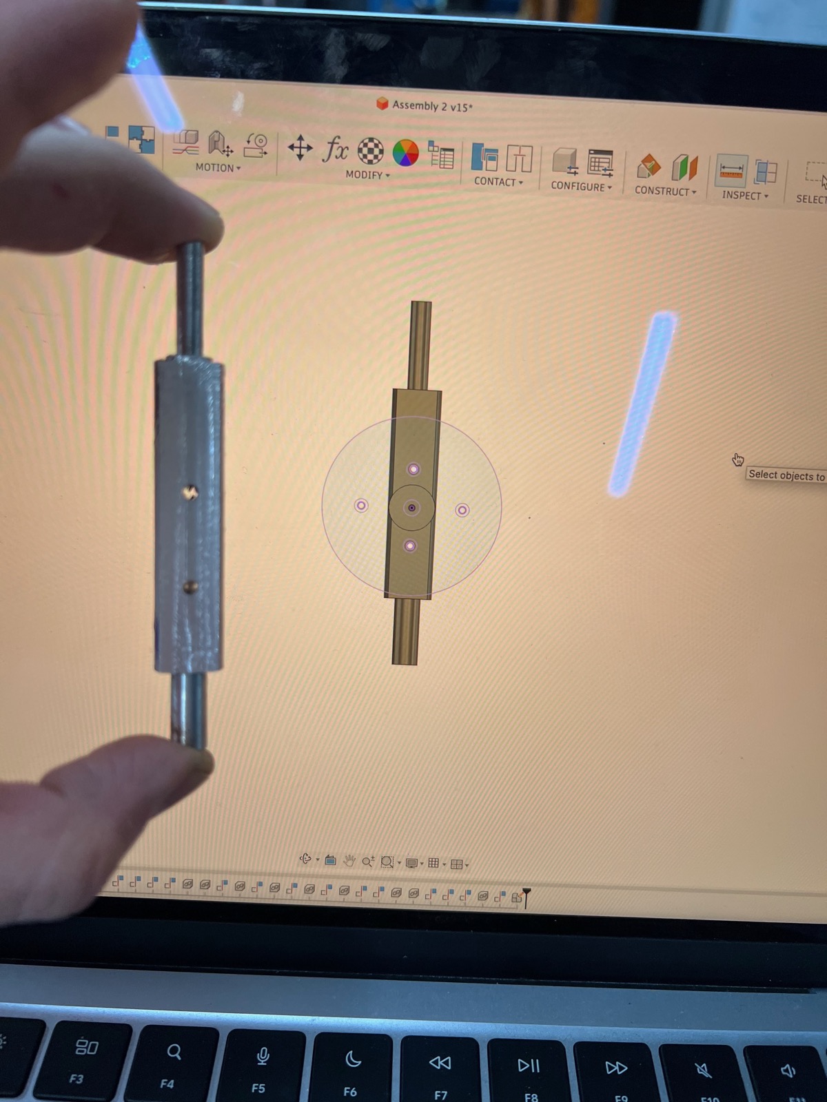
Terror struck me as I realized I would need to machine a rod to connect the reaction wheel to the rotational gimbal. The rod would need three radius, one for the slip ring, the next for mounting the motor, and a third for the connection to the gimbal.
Lucky enough, ITP has a lathe and I was able to get on it, for the first time since high school. It felt good to spin the dials again.
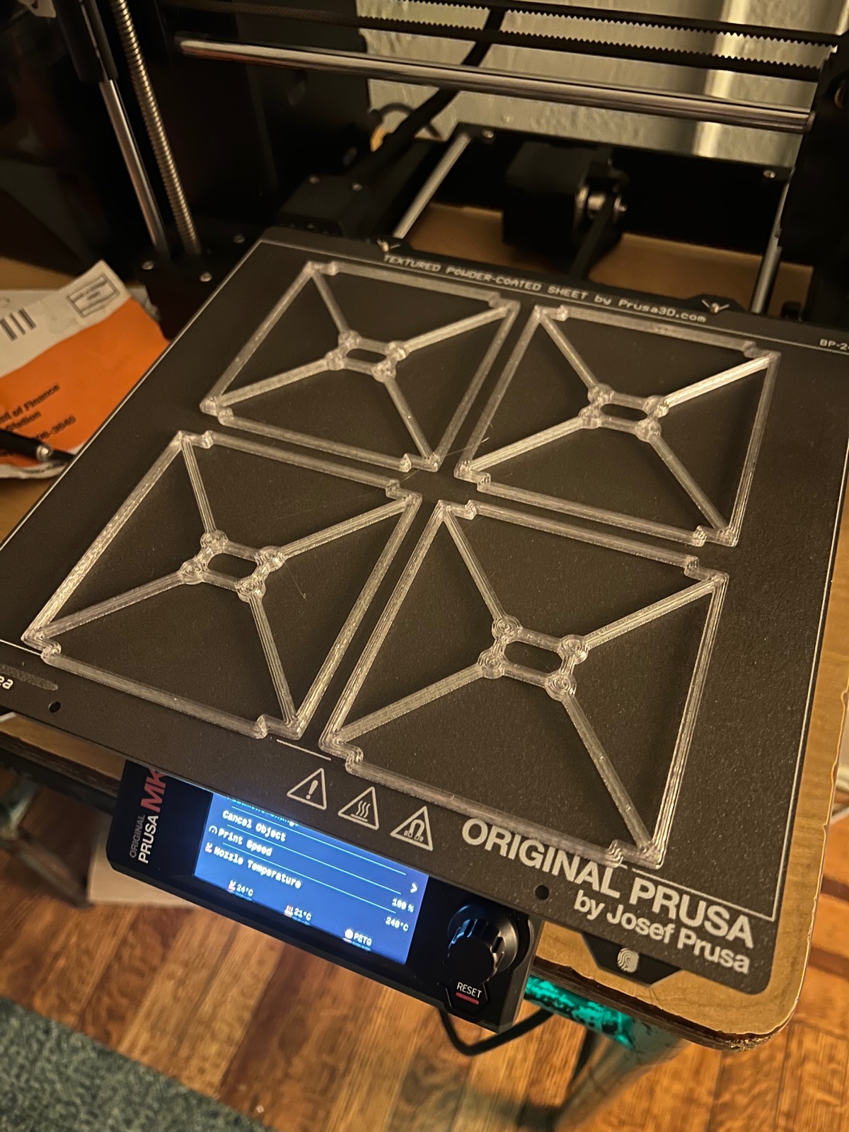
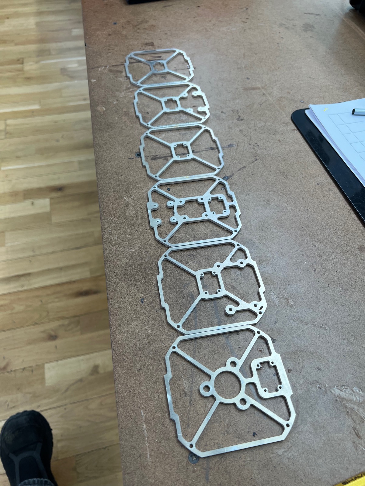
Then, I fabricated the sides of the cube on the metal laser. I had been chasing down the idea of doing them with a CNC, but ultimately this was too much complexity, it was easier to do them in 2d.
That same day, I machined the mounting holes for the bldc motor to the shaft. This required facing the shaft and positioning two holes.
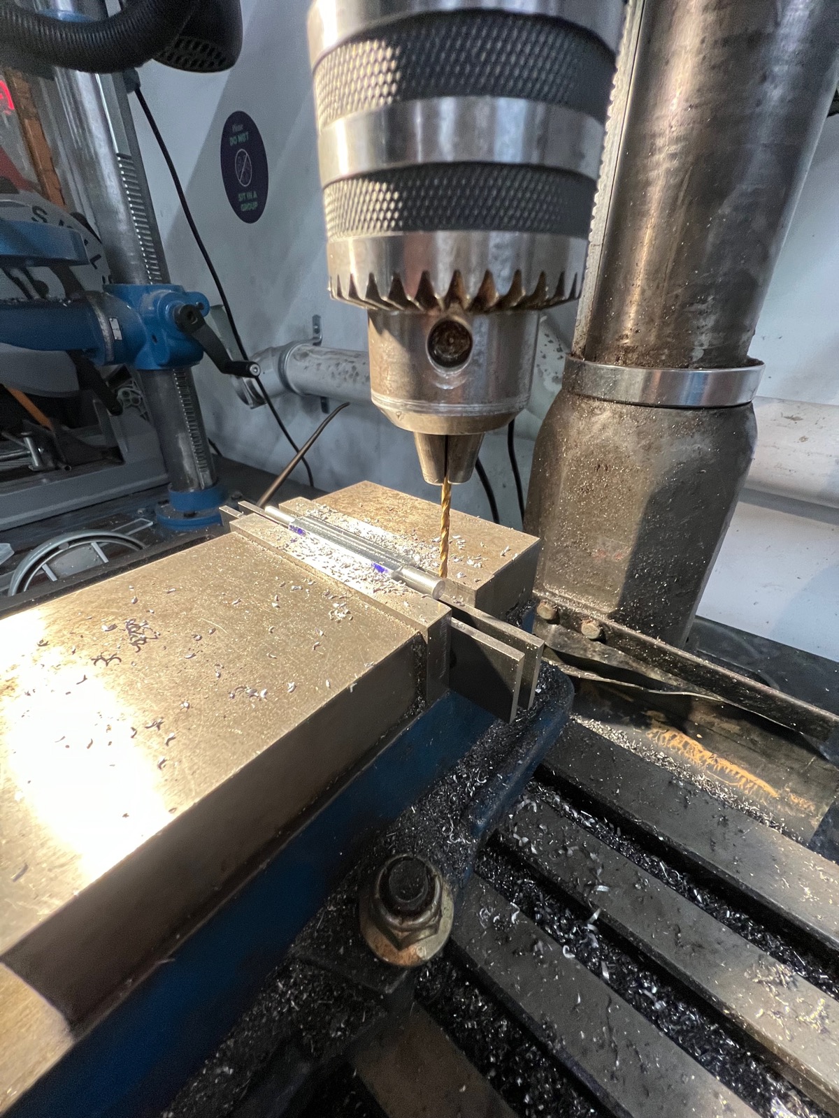
Getting on the machines again for the first time in a long time was exciting and terrifying. As the time per operation began to stack up, mistakes were becoming costly. I am happy with the outcome. The motor mounted to the axis smoothly.
The additional lip is to allow the cables from the slip ring to pass through.
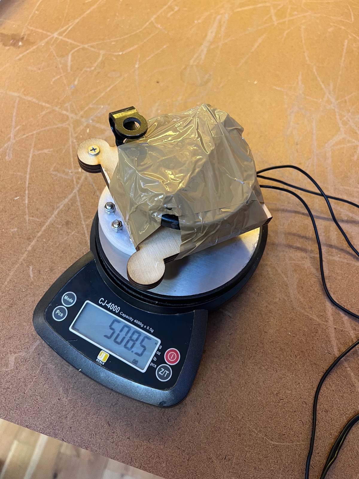
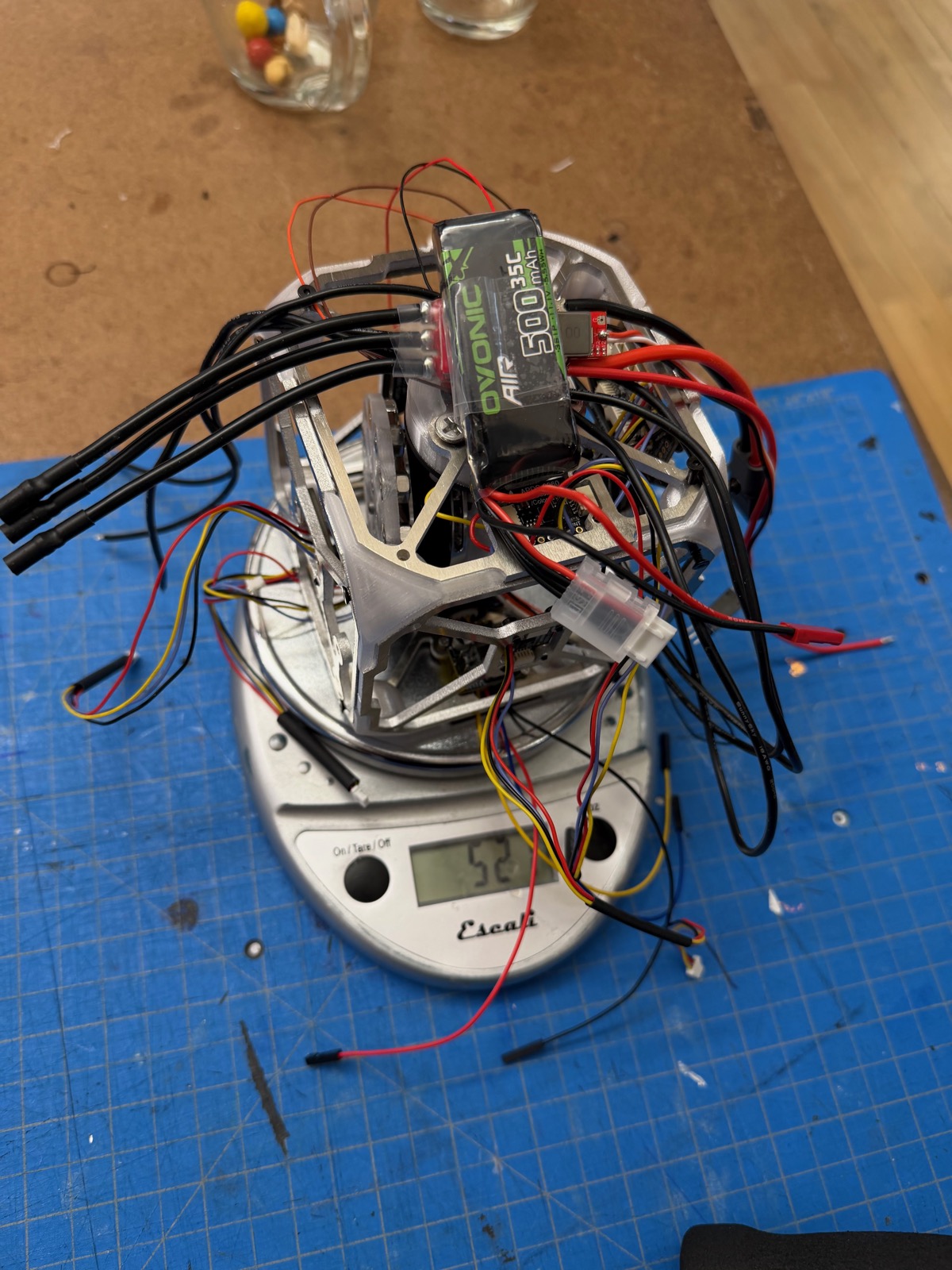
Everything came in under weight, thank god.
The first assembly came together really sloppy, the corner mounts I had designed were throwing in all kinds of interference and moving the mounting panels around weirdly. Poor tolerances stacked up.
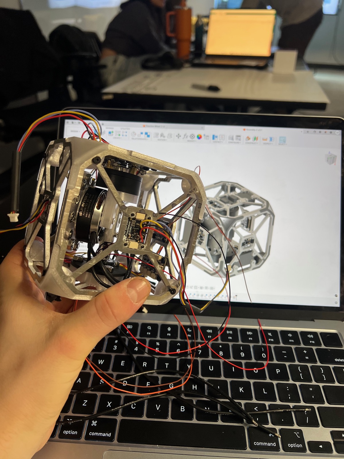
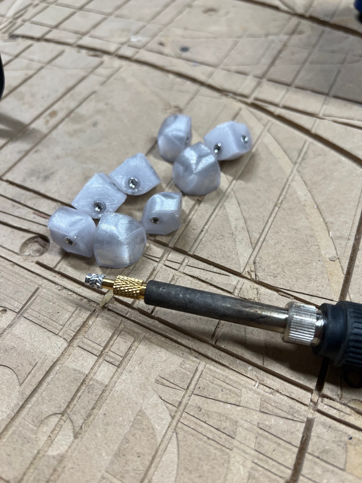
I designed new ones without the edges on them, just faces and holes. I learned a lesson, the mates in Fusion 360 translate well to actual assembly strategy. Where overconstraints occur, the physical design will probably over constrain as well.
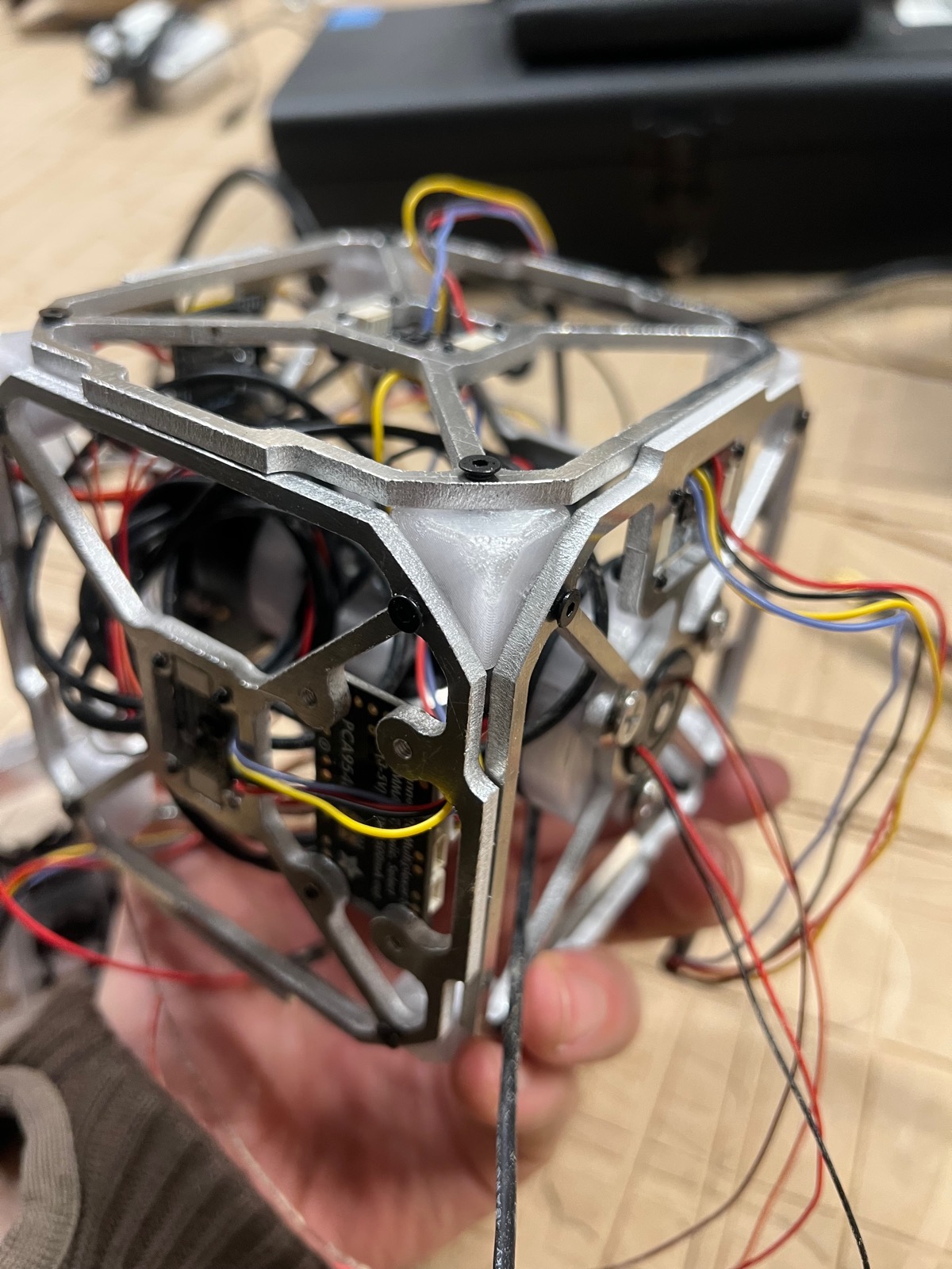
The assembly was coming together hellishly. Wiring was a whole beast I had not expected. Tons of custom cables. The bright side was this beautiful organic look of vine like wires. The cube started to look evolved.
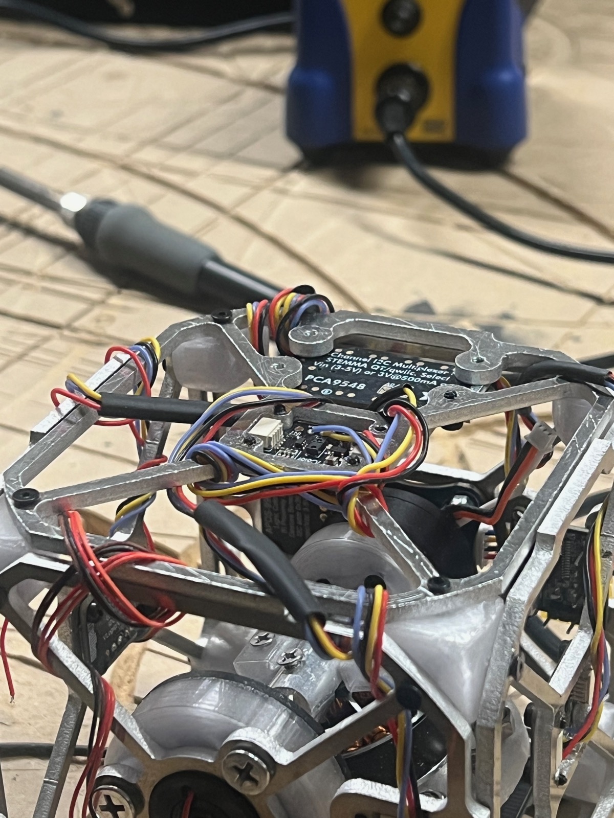
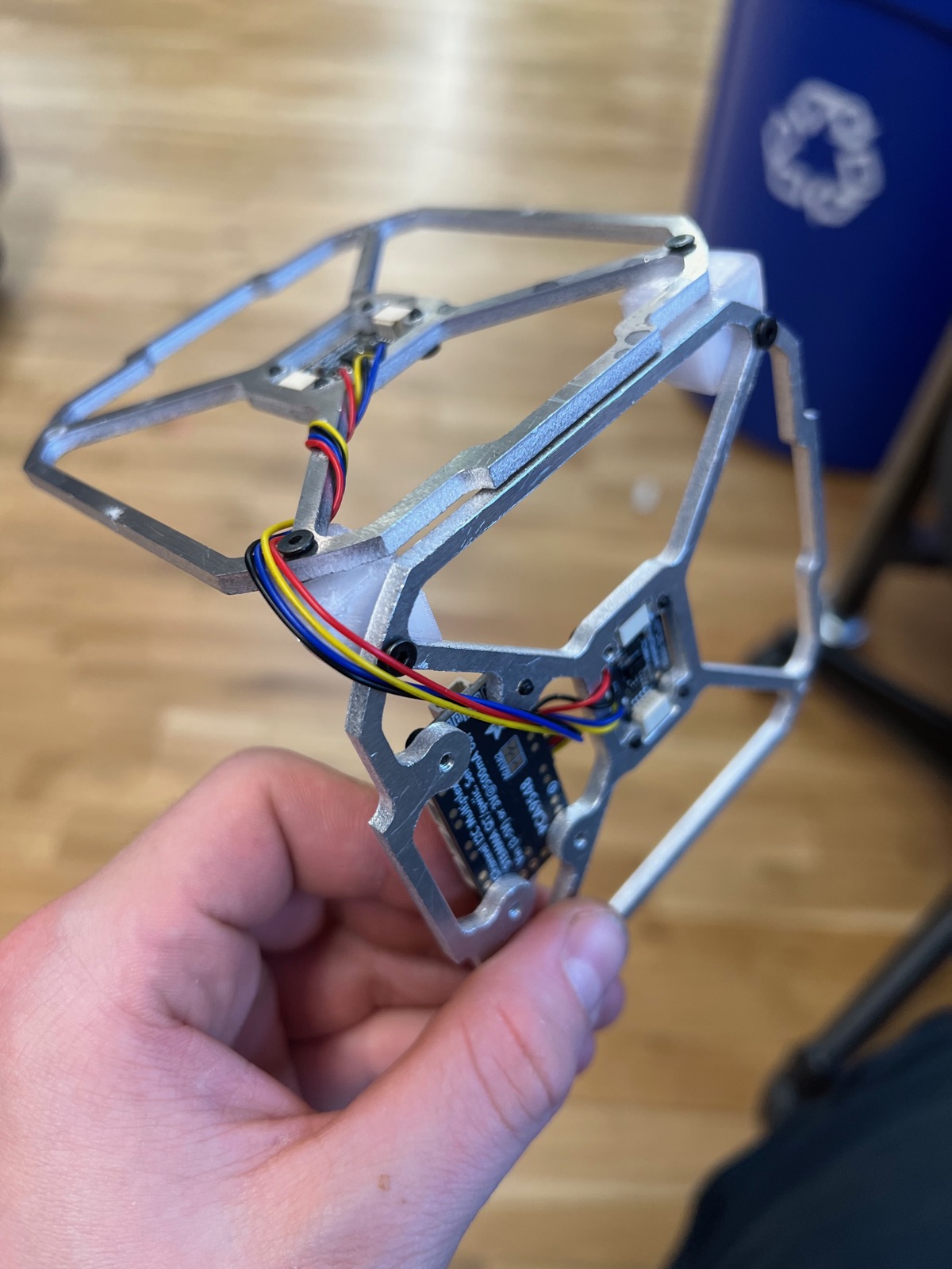
This meme made me laugh and think about how to wire in a non engineering way.

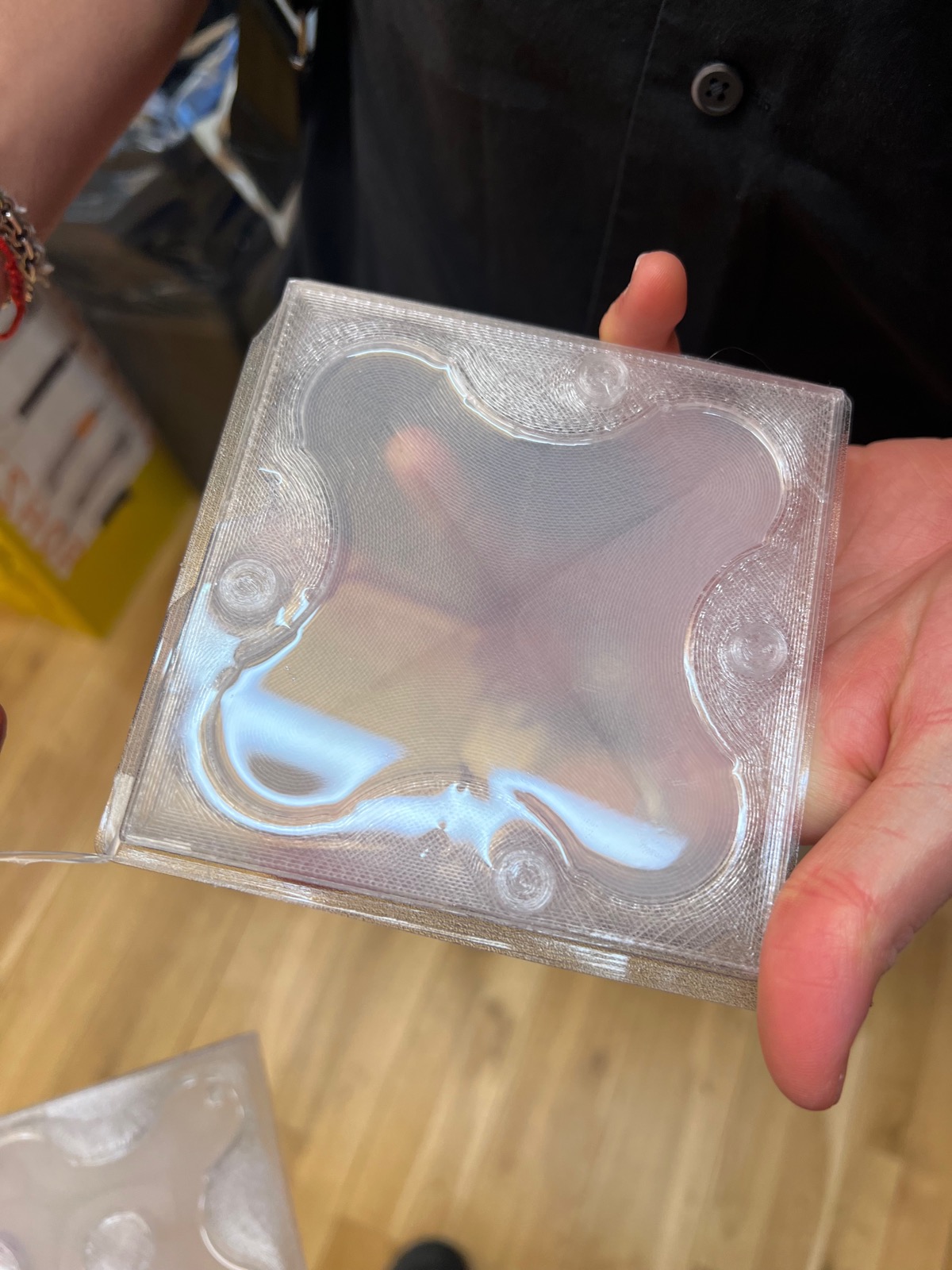
With the wires starting to take shape on the outside of the cube, I realized we needed a way to protect them. I started to think about positioning silicone deposits on the outside of the cube to provide a protective layer. Like fat on veins on bones. I started to think about it as inflatable pads, but Kari advised me to stick to regular deposits and not to add complexity.
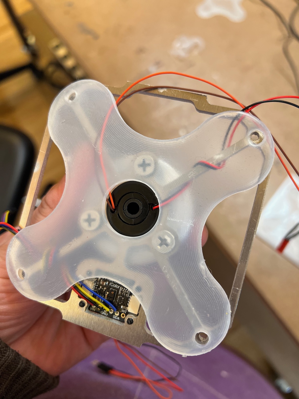
Finally, William and I were able to get together again to start programming it all together. Everything powered up and connected. We were able to get the motor spinning again.
I mounted the battery to the back of the central rod with double sided tape and zip ties. When we tried to run everything off the battery, the ESP would fry.
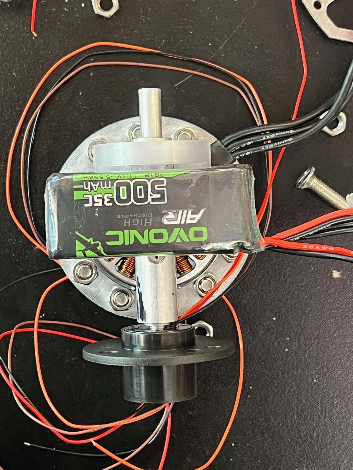
The current state of the project is an unassembled pile. We are unable to get it to run off battery power without the ESP frying. The cause is unknown.